|
RESIDUAL GASES AND RELATED TOPICS IN VACUUM TUBES
by Rene M. Rogers
Sr. Scientist
1995 It has been said that vacuum tubes, sooner or later, bring those who work with them face to face with every facet of Nature on the grand scale. Whatever the merits of that, I have had numerous occasions to scour the lore and review the fundamentals in an effort to explain a myriad of strange observations made over the past 40 years in the vacuum tube business. In 1968, for example, I was working as a general troubleshooter on a backward wave oscillator production line which had just been consolidated with a low power klystron line. The crisis I had been working on was near resolution so my new boss assigned me to work on a series of chronic problems in small klystrons which might or might not have a common thread associated with "residual gases". The term "residual gas problem" had come into general usage on the production line to describe some things people were seeing. My observations following this assignment over the next two years had a profound effect on my concept of the subject and forced me to adopt radically different views than I had previously gathered from the lore of a generation of old time vacuum tube experts.
Instead of presenting this material in the usual manner with theory
first followed by the supporting experimental data, I will try to recall
the findings in chronological order and encourage my reader to engage in
his own speculations as well as follow the development of the theory
favored by myself. In the
end, the curious reader may be left with some tantalizing questions.
Unfortunately, all economic incentives to follow up on this
material and do some basic research in the field have long since vanished. A fuller understanding must await a few inquisitive people
who can gather bits of seemingly irrelevant data along the way to other
places and eventually put them together in their leisure hours.
By way of my initiation, one of the production engineers took me to
a bench where a reflex klystron, just returned from a customer, was being
tested. The operation of the
tube was normal in all respects except that the repeller voltage was out
of specification. A small
percentage of our reflex klystrons had been returned from the field on
this account since the beginning of time.
No one knew why and the cost of a serious effort to find out was
estimated to be far in excess of the cost of a few replacement tubes.
The interesting thing about this particular tube, however, was the
visible glow from within which could be seen through the clear mica
window. The tube was gassy and people were beginning to ask why
returned tube failure records were showing high gas levels as the cause of
more and more failures. Of
course, failure records are usually prepared by people who have little or
no concept of the operation of the device in question, but the records are
useful nonetheless because troubleshooters learn to read between the
lines. My guess is that gas levels had not changed as much as the
record keeping procedures.
I brought a microscope over to the test set and soon had the
interaction gap in focus with the beam on.
A blue glow was clearly visible where the electron beam crossed the
gap. The engineer told me that he had seen the phenomenon many
times and believed it was due to the fact that the tube had a very small
leak. He was of the opinion
that the glow was due to the ionization of O2 and N2 from the air that
seeped in through this leak. Leaks
of this sort were too small to be detected by the very sensitive helium
leak detectors that are used routinely in the vacuum tube business to find
larger leaks during production. The
tube we were looking at had been in operation in the field for several
hundred hours before the customer noticed that he could no longer adjust
the repeller voltage to achieve proper operation.
Other tubes with identical symptoms had recently been returned as
well. These were routinely
opened for inspection, but nothing unusual was found.
Some were fitted with new exhaust tubes and subjected to the most
rigorous leak testing methods known using the helium leak detector, all
with negative results.
Several years earlier I had been responsible for instrumentation in
support of a group of researchers working on gas lasers and had become
somewhat familiar with photoemission spectroscopy.
This work had been abandoned and much of the equipment was stored
in a warehouse gathering dust. The
company had several warehouses full of such material.
It was too valuable to dump or sell to scrap merchants for pennies
on the dollar, but most, if not all of it had zero book value and very few
people had any idea what there was or what it might be good for.
I retrieved one of the small spectrometers which covered the band
from 3000 to 7000 Angstroms more or less and set up a small dark room on
the top of a lab bench. Using
a couple of lenses, I made an image of the klystron gap on the entrance
slit of the spectrum analyzer and soon had a chart recording of the
emission spectrum of the gases inside the tube.
All of the principle lines were in the H2 spectrum and there was no
evidence of O2, N2, CO, or CO2, or any other likely component.
There were some lines not listed in the CRC Handbook, but these
were all at levels just above the noise floor.
One measurement is easily worth 1000 calculations or, perhaps,
10,000 speculations.
In connection with the earlier laser studies, I had prepared a
series of glass ampules with two electrodes each and gas samples of H2,
N2, O2, CO, CO2, argon, and helium, all at a pressure of roughly 10-3
mmHg so that a low voltage glow discharge could be established in each.
These were now lost and had to be made anew.
Commercial neon pilot lamps were available from the stockroom.
I used these sources to calibrate the spectrometer and prepare
charts of the various spectra for comparison.
The principle lines from each source compared very favorably with
the tables in the CRC Handbook although there were always a few weak lines
which may have been due to trace impurities in the samples and/or
omissions in the tables. In
any case, it was very compelling to compare a spectrum from a klystron gap
to one or another of these charts. I note in passing that there were also unmistakable traces of
argon and xenon in the commercial neon lamps.
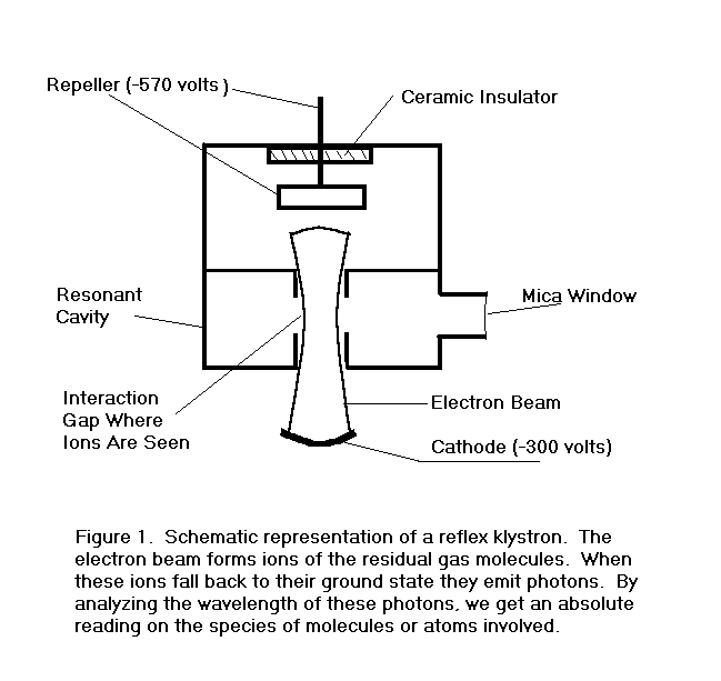
Figure 1. is a schematic representation of a reflex klystron. Such a contraption with a transparent window is an ideal
vehicle for the study of residual gases in small sealed-off vacuum tubes.
The operation of the device is described roughly as follows.
The electron beam passes through the interaction gap where it is
velocity modulated by an rf field established there by previous electrons.
The velocity modulated electrons leave the gap and enter a drift
space with a retarding electric field whose strength is set by a negative
voltage on
|
|||
|
FIGURE 1.
All of the electrons are turned around by the retarding field and
re-enter the interaction gap. If
the repeller voltage is properly adjusted, the velocity modulation on the
electrons entering the drift region will be largely converted to density
modulation, or bunches, of the right phase to reinforce the rf voltage at
the gap when they return. The
gap is part of a resonant cavity which determines the central operating
frequency of the device. The
exact frequency, however, can be pulled slightly by adjusting the repeller
voltage and thus the phase of the returning bunches.
However good the vacuum is in any device, there are always a large
number of gas particles present. For
practical purposes, the vacuum is poor when a significant percentage of
the beam electrons collide with one or more of the residual gas particles
during the transit time between leaving the cathode and eventual
collection at a positive electrode, in this case the cavity resonator.
The vacuum is good when an insignificant fraction of the beam
electrons experience a collision. A
collision entails a random change in velocity and transit time which shows
up as noise in the rf signal. There
are many sources of random noise in the rf signal and gas levels at which
ion noise becomes important are usually high enough to cause other
problems. Very roughly
speaking, a residual gas pressure of 10-4 mmHg is unacceptably
high in terms of ion noise as well as ion erosion of the cathode, while 10-6
mmHg will not lead to ion noise in excess of noise from other causes and
the effects of ion erosion will be evident only after operation for
several thousand hours. Residual
pressures in the range of 10-8 mmHg or lower are typically
considered ideal.
The pressure in a reflex klystron can be measured in the
approximate range 10-3 mmHg to 10-7 mmHg within a
factor of 2 or 3 by measuring the ion current to the repeller.
The electrons in the retarding field region collide with and ionize
some of the residual gas particles and the positive ions thus formed flow
to the negative repeller. In [1]
we calculate the rate of ion formation for a given beam current and path
length in terms of the pressure and the collision cross section of the
atoms in question. This
technique is also applicable to almost any vacuum tube with a control grid
by operating the grid at a positive potential and the anode at a negative
potential relative to the cathode. No
electrons from the cathode will reach the anode under these conditions
while the ions formed between the grid and the anode will mostly flow to
the anode where they can be collected and measured.
The high pressure limit mentioned above is ill defined, but the low
pressure limit is set by the formation of soft X-rays.
The spent electrons are collected at the walls of the resonant
cavity at a potential of several hundred volts and the sudden change of
velocity of the charged particles give rise to photons (X-rays) with
energies up to the beam voltage. These
photons are energetic enough to produce photo-emission at the repeller and
we have no way to determine whether an electron flowing to the repeller
does so to replace a photo-electron or to neutralize a positive ion.
The ion current becomes small as compared to the photo-emission
current at around
The pressure in the klystron I looked at first was on the order of
10-5 mmHg, typically 2 or 3 orders of magnitude greater than
new tubes of this type. During
continued observation, however, both the ion current and the intensity of
the H2 spectral lines decreased slowly.
There was also a pressure transient at turn on after any extended
period of quiescence during which time the cathode was hot but no beam
voltage was applied. Unfortunately,
the notebooks, recorder charts, and oscilloscope records of those
experiments over the next two years are not available to me, so I must
rely on my memory which is much better with regard to the conclusions I
drew than to the data on which those conclusions were based.
To a first approximation, the pressure increased in direct
proportion to the time that the beam current was turned off as indicated
by both the initial ion current at the repeller and the initial intensity
of the H2 lines when the beam was suddenly turned on.
After turn-on, the pressure decayed exponentially to a quasi-steady
state level with a characteristic time constant of roughly 5 or 10
seconds. From the rate of ion
formation, the volume of the tube and the basic considerations set forth
in [2]
regarding pressure transients, I estimated that between 1% and .1% of the
ions thus formed were somehow driven into the walls or otherwise trapped
so that re-entry into the vacuum would take much longer than 5 or 10
seconds. When beam current
was flowing, the device was acting as an ion pump, less inefficient than a
conventional sputter ion pump, perhaps, but not a negligible factor
either. The walls of the device, on the other hand, were acting as a
relatively steady source of H2 influx, at least so long as the temperature
remained constant.
After several weeks of studying this phenomenon, the ion current at
the repeller became small compared to the X-ray current and the spectral
lines became almost undetectable. When
shipped, perhaps a year previously, the klystron required a repeller
voltage 270 volts below the cathode voltage to work at the desired
frequency. It now required 290 volts, but the beam current and the
output power were substantially the same as when the tube was new.
There were several field return reflex klystrons of the same type
on hand which had similar symptoms as well as a stock of new ones and I
spent a lot of time examining them. All
of the field returns required a more negative repeller voltage, from 2 or
3 volts up to 30 volts, than they did when they were shipped, but not all
had measurable gas levels. The
ones that did show gas, however, had H2 as the only detectable species
although there were some very weak lines not apparent in every tube.
For the most part, the new tubes had gas pressures below detectable
levels, but traces of H2 which vanished entirely after several hours of
operation were seen in one or two. One
new tube exhibited a strong spectrum of CO and CO2 which diminished to
undetectable levels after several days of continuous operation.
My speculation is that the cathode was not completely broken down
before the tube was sealed off the pump.
I never saw a recurrence of this phenomenon.
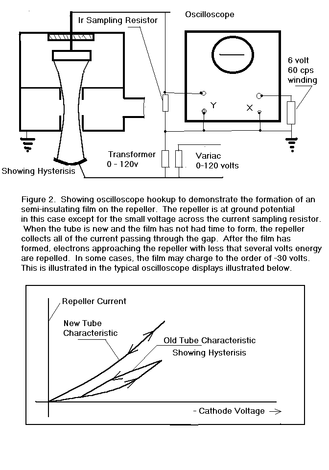
The relationship between gas levels and repeller voltage shift was
obscure at best, but it soon became clear that some form of
semi-insulating layer was attaching itself to the surface of the repeller.
I connected several klystrons as shown in Figure 2. and found that
the form of the repeller current vs. cathode voltage function was quite
dependent on the age and history of the tube.
In this configuration, the klystron behaved somewhat as if there
was a leaky capacitor in series with the repeller after the tube had been
operated for several hundred hours or more.
It was well known that barium evaporated from an oxide cathode even
under perfect vacuum conditions and that sputtering by ions under less
than perfect conditions would increase the rate.
It was also well known that barium is a getter of a variety of
residual gases in vacuum tubes. I
could therefore guess that a barium film on the repeller surface was
gettering at least some of the gases in the klystron to form a
quasi-insulating film. To
test this hypothesis, I put a positive bias on the repeller voltage in the
above configuration so as to heat the repeller to several hundred degrees.
The klystron was filled with H2, and only H2, to a pressure in
excess of 10-3 mmHg. The
repeller current display returned to that of a new tube and the frequency
vs. repeller voltage characteristic returned to the values recorded when
the tube was new.
The evolution of barium from an oxide cathode is a very complex and
poorly understood process which depends rather critically on the cathode
temperature as well as sputtering by ion bombardment.
It is easy to imagine that the rate of formation of a barium film
on the repeller in a reflex klystron could vary widely from tube to tube
even though all are built by the same people using routine parts and
processes. Barium is very active chemically and forms stable compounds
with all but the noble gases, including BaH2 which has a heat of formation
of approximately 1.8 ev. It
is doubtful that there was ever enough hydrogen available to form
stoichiometric BaH2, but is seems as though a barium film which has taken
up some H2 will hold a charge from a few volts up to 30 volts when
subjected to a steady ion current from collisions between the residual gas
and beam electrons in the retarding field region[3].
It also seems reasonable to suppose that a barium film which has
taken up enough hydrogen to become partially insulating will disgorge
enough hydrogen to flood a klystron to an uncomfortably high pressure when
a small spot of it is involved in a severe arc.
I encourage my reader to do a back-of-the-envelope calculation
assuming that a barium film several thousand Angstroms thick has taken up
hydrogen atoms on a one-for-one basis, or some fraction thereof, and find
the size of a spot which, if vaporized during an arc, would release enough
hydrogen to raise the pressure in a typical klystron to a pressure of
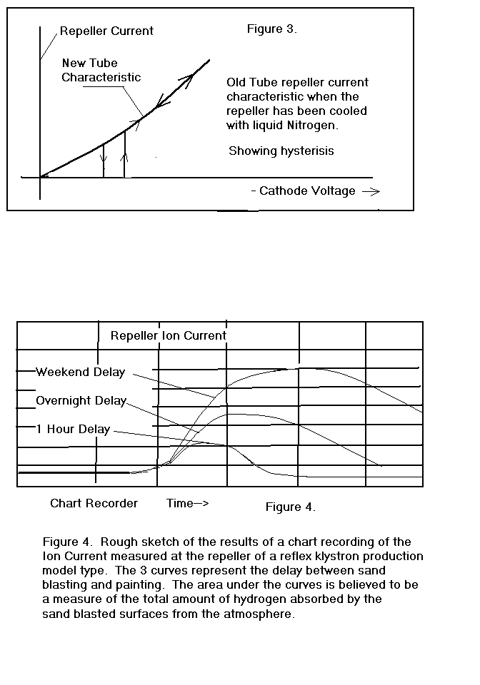
During the course of observing these phenomena, I happened to use
some liquid nitrogen to cool one of the klystrons and noticed that the
repeller current characteristic changed dramatically as indicated in
Figure 3. There was no
measurable repeller current until a threshold voltage was reached and then
the current changed discontinuously to the value it would have had if
there was no film. There was
also some hysterisis observed in this characteristic.
As the repeller temperature returned to normal, the characteristic
returned to normal in a continuous manner.
Some friends in a division of the company working with
semiconductors came over to see this phenomenon and quickly set forth a
variety of scenarios familiar to them to explain it all, but they agreed
that an exact understanding would require more study than any of them
could fit into their busy schedules.
A small mystery at this point was my failure to see N2 in any of
these tubes because H2 and mass 28, ie N2 and CO, as well as CO2, were
routinely observed during and after bakeout in a vacuum station carefully
designed specifically to study the evolution of gas species before,
during, and after bakeout. Species
identification was done using a mass spectrometer which was sensitive to
partial pressures down to 10-10 mmHg.
The mass spectrometer was not inside the bakeout oven, but it was
baked to some degree using electrically heated fiberglass tape wrapped
around it. I suspect that
this bakeout was never adequate and that the mass spectrometer, and/or its
connecting tubulation, was the source of the N2 and perhaps some of the CO
and CO2 as well. In any case,
I never saw spectral lines of N2 or O2 in a sealed off vacuum tube during
the next 2 years although I looked very hard for them.
Perhaps, I reasoned, the leak channels are too small to admit big
atoms like N2 and O2 or even helium, but are large enough to admit H2. I stored my original specimen, now with a hard vacuum, in an
H2 atmosphere overnight with no voltages applied and looked for evidence
of gas the next morning. H2
lines and repeller current above the X-ray floor were evident if I looked
very hard and used my imagination. With
only the heater power on and no waveguide connection to drain away heat,
the temperature of the klystron body would reach roughly 60 DgC, too hot
to touch comfortably, and with full voltage and beam current on the
temperature would go over 120 DgC. The
next night I applied heater and beam voltage to the tube, set a recorder
with a logarithmic response to measure the repeller ion current, and
provided an H2 atmosphere for the tube.
When I came to work the next day I could hear the recorder motor
grinding against the stop from far down the hall.
The H2 pressure inside the tube was too high to measure.
The heater current was high because heat conducted by the H2 was
now a significant factor in the thermal network of the heater-cathode
system and the heater was cooler than normal.
This familiar diagnostic indicated a pressure in excess of 10-3
mmHg, a level consistent with the repeller ion current I observed.
The beam current available was roughly half of normal because the
cathode was somewhat poisoned and there was a visible film on the mica
window, but the spectral lines of H2, and only H2, were still apparent.
It is well known that the ions of residual gas particles formed
between the cathode and the anode will fall into the cathode with energies
up to the applied voltage and dislodge, or sputter, atoms of the cathode
material. The sputtered
cathode material travels in a straight line from the point of origin and
tends to stick on whatever surface it strikes.
Atoms striking a hot surface, such as the grid at the gap, may
re-evaporate and move on with some going to the mica window.
If all of the cathode coating is sputtered away, the cathode will
generally not emit electrons, but if some coating remains the cathode may
often be brought back to life by simply keeping it hot and drawing some
current from it. This
eventually happened in this case and the gas pressure also decayed to
barely detectable levels as well over a period of several weeks.
I assumed that whatever leak channels were responsible for
admitting the H2, they became markedly more permeable as the temperature
increased.
One day, while examining new reflex klystrons from the inventory
awaiting shipment, I found one with a faint glow in the gap that, to the
naked eye, had a slightly different color than the now familiar H2
spectrum. The ion current at the repeller indicated a pressure on the
order of 10-7 mmHg while spectral analysis proved the gas to be
a mixture of argon and neon with no evidence of H2 or any other gas.
Moreover, the principal neon lines were stronger than the principal
argon lines, which may or may not indicate anything about the relative
abundance of these gases in the tube.
Argon is roughly 1% of the atmosphere (presumably from the
radioactive decay of potassium over the past 4.5 billion years) while the
partial pressure of neon in the atmosphere is roughly 10-3
mmHg. If this tube had a leak
to air, where was the N2 and the O2?
A list of collision cross sections for various gas particles is
shown in Table I, but the range of values is too small to inspire me to
believe that size is an important factor in all of this.
After several days of operation with the beam on, the spectral
lines and the ion current decayed below detectable levels.
It would appear that the beam was effective as an ion pump for
argon and neon as well as H2, CO, and CO2.
This did not surprise me, for I supposed that the pumping mechanism
included simple burial of ions impacting solid surfaces with energies of
10's or 100's of electron-volts as well as the formation of exothermic
compounds between some gas species and the metal walls of the tube.
The next experiment was to put the tube in an enclosure filled with
helium while recording overnight the ion current at the repeller with the
beam current on. The repeller
current was in the X-ray limit range at the outset and for roughly 8 hours
thereafter, but then the pressure began to rise at an ever increasing rate
to the level of roughly 10-6 mmHg after 14 hours.
Helium lines, and only helium lines, were clearly evident in the
spectrum. After beam pumping
had been allowed to bring the helium pressure below detectable levels,
several days, this experiment was repeated with the tube in an argon
atmosphere. The influx of gas
was evident after roughly 4 hours and the recorder motor was grinding
against the stop after 14 hours. The spectrum showed the gas to be argon and nothing else.
It was pretty clear that the size of the particles, as determined
by their ionization cross sections, had little or nothing to do with what
was going on here.
In discussing these findings with colleagues, I learned of a report
written by people at a subsidiary of the company.
They had attached a bakeable mass spectrometer to a large klystron
with an oxide cathode in order to study residual gas species present
before, during and after normal processing, which included bakeout and
pinch-off. They found H2O,
H2, CO, CO2, and CH4 before and after bakeout and pinch-off, but no O2,
N2, argon, neon, or helium. The
total pressure after pinch-off was 5x10⁻⁷ mmHg.
This decayed to 2x10⁻⁹ mmHg of H2 after 400 hours of
operation. To me, the
striking thing about this report, in view of my recent findings, was that
after 500 hours of operation the tube developed a leak to air which became
evident by the appearance of argon at the mass spectrometer.
O2 and N2 were never observed before the total pressure was too
high to continue applying beam voltage.
It would appear that O2 and N2 are quickly captured and tightly
held by the inner surfaces of the klystron or by the walls of the leak
through which the argon was able to pass relatively unhampered.
The electron beam was on most of the time so ionization and
disassociation of any gas molecules in the path of the beam is to be
expected. The ions will, of
course, be accelerated by the strong electric fields present in the
klystron and will collide with solid surfaces with considerable energy.
Recalling that 1 electron-volt is the energy equivalent of 11,600
degrees Kelvin, we can imagine that the chemistry of ionized and
disassociated gases in a vacuum tube is not the same as the chemistry in a
laboratory vessel at room temperature.
One of the chemists also produced a paper perhaps 10 or more years
old reporting the results of a series of experiments in gas diffusion
through capillaries of various materials.
The experimental apparatus consisted of two bakeable chambers which
could be independently evacuated and back-filled with various gases.
Each chamber included a bakeable mass spectrometer for measuring
the partial pressure of individual gas species.
The chambers were connected by a long capillary tube which could be
made of glass or metal and coated with various materials like oils or
pyrolytic graphite or left plain. The
basic idea was that the expected transit time for a gas particle entering
the capillary at one end to emerge from the other end could be calculated
exactly in terms of a model in which each encounter with the walls is
followed by an instantaneous cosine law rebound.
The actual transit time was always considerably longer than
calculated and a new model was offered to explain the experimental
results. In this model, each
encounter between a gas particle and the wall is characterized by a
sticking probability and, once stuck, by a residence, or sojourn, time.[4]
Neither
the chemist nor I could follow the mathematical theory, a fact which
inspired me to take a graduate course in random variables, but we all
agreed that the results could be explained only if the diffusing gas
particles spent considerable time in a semi-bound state along the way.
This was true for the noble gases, helium, argon, and neon as well
as the chemically active gases, O2, N2, H2, CO, and CO2.
The noble gases may not form stable compounds, but they do form
tenuous bonds with almost all solid surfaces.
Furthermore, the evidence of beam pumping for the noble gases
suggested that their ions were being driven deep within a solid wall and
held interstitially for long periods of time.
There were, of course, books on the subject of high vacuum as well
as professional societies interested in the subject, but most people in
the dying vacuum tube business were concerned only on a casual basis if at
all. I bought a 1968
publication [5],
got a copy of Dushman[6]
from the company library, and dug in.
I also reviewed my lab notes regarding some experiments I had done
a dozen years earlier with a brighter-than-average co-worker with a PhD in
physical chemistry, long since departed to form his own company, when we
had occasion to measure the diffusion parameters of sulphur in 18-8
stainless steel. The details
of that experiment are lost, but I used the same technique to make the
same measurements in 1970 with regard to Zinc in a Copper-Nickel alloy. [7]
One doesn't have to read very much in Dushman to learn his view
that metals dissolve prodigious amounts of a wide variety of gases and
release them back into the vacuum or out into the external environment
following the laws of diffusion. In
his model, molecular gases disassociate into their constituent atoms at
the surface of the metal and migrate into the solid lattice where they may
reside interstitially between the metal atoms or, in some cases, replace
one of the metal atoms. The
residence time for a gas atom in one of these configurations depends on
the binding energy, called the heat of diffusion, and the temperature.
The relationship is t0 = eQd/kT/f0
Seconds, where t0 is the expected residence time in Seconds, Qd
is the heat of diffusion in electron volts, k is the Boltzman Constant,
and T is the absolute temperature in Degrees Kelvin.
kT is approximately 0.025 ev at room temperature, while f0
is the frequency of escape attempts per second.
Roughly speaking 1012 < f0<1013
per second. Binding energies
range from a fraction of an ev to several ev with the result that expected
residence times range from nanoSeconds to the age of the universe in our
everyday experience. Dushman
also discusses a parameter of scale, a diffusion skin depth somewhat
analogous to the more familiar rf skin depth, which describes how far
dissolved atoms will migrate in a solid for a given time and temperature.
All this is discussed further in the reference[8].
There was very little data available regarding the diffusion
parameters for gases in metals and even less agreement in the data that
was available, but I was able to estimate on a very rough basis that the 1
hour diffusion skin depth for H1 in iron at 120 DgC was on the order of
one millimeter. Since the
bodies of the klystrons I was studying were made of iron several
millimeters thick on average, it was not surprising that I was able to
achieve a hard vacuum using beam pumping for several days or weeks or that
storage in a hydrogen atmosphere overnight would produce the results
observed. These findings were
met, however, with howls of outrage from several of the old timers, some
in high places, for it went directly against the core lore that all
residual gas problems were either internal surface phenomena or leaks to
the outside air. I was
familiar with the table napkin calculation to the effect that there are on
the order of 1016 surface traps/Cm^2 on a metal surface and
when each of these is occupied by a gas particle the surface is, by
definition, covered by a monolayer of adsorbed gas.
Since there are roughly 3.5x10¹⁶ gas particles/Cm^3 in a
vessel at 1 mmHg (from Avogadro's Number), the pressure in a 1 liter
vessel would be on the order of .17 mmHg if all of the particles in a
monolayer were suddenly released. The
purpose of the bakeout procedure, according to my critics, was to dislodge
these surface gases and, at the very most, a few gas particles trapped one
or two atomic layers below the surface.
When lines such as these are drawn in the sand, the facts of the
matter become totally irrelevant and further discourse is not possible.
It was pretty clear to me how gas atoms and molecules inside the
vacuum became ionized by the electron beam and disassociated and
accelerated to enormous temperatures by various electric fields and how at
least some of these ions would be deeply imbedded in the metal walls, but
the reverse process at the outer surface was somewhat obscure.
The heat of formation of 2H1 -> H2 is roughly 4.5 ev while,
according to Dushman and others, only atoms of hydrogen can go into
solution with a metal. Even at the melting point of copper, 1083 DgC, over half of
the molecules of H2 in a hydrogen furnace have kinetic energies less than
0.1 ev while, according to Boltzman Statistics, only 1 in 1017
have energy in the neighborhood of 4.5 ev.
Yet, according to experience and the literature, all metals which
have been on a trip through a hydrogen furnace at red heat and above come
out with hundreds to thousands of parts per million of H1 dissolved
throughout. Where does the
energy required to break the molecular bonds come from?
The most plausible scenario seems to be that some molecules on the
surface become atoms within the solid lattice by means of quantum
mechanical tunneling. Once
dissolved as atoms, H1, at least, diffuses so rapidly at elevated
temperature in most, if not all, metals that the distribution becomes
uniform relatively soon in objects the size of vacuum tube parts.
Volume solubility is, therefore, a surface phenomenon. At equilibrium, gas molecules arrive at the surface and a few
of them are dissolved as atoms at a certain rate while from within atoms
diffuse to the surface and re-combine and re-enter the gas phase as
molecules at the same rate. The
surface concentration at equilibrium is established throughout the volume
at a rate dependent on the temperature, the diffusion parameters, and the
size of the object. The
volume solubility of diatomic gases in metals is proportional to the
square root of the pressure in the gas phase over the widest possible
range of pressures. This
principle is known as Seivert's Law and is a consequence of the fact that
dissolved atoms do not re-enter the gas phase as such, but must pair up at
the surface to form molecules.
The equilibrium pressure inside a void below the surface is
enormous, typically millions of atmospheres, so that once a blister has
begun to form in any metal in which gas atoms are dissolved, it will grow
without limit until the metal is eventually ruptured.
Vacuum tube lore tends to attribute the observation of blisters on
copper coming out of a brazing furnace to the presence of oxygen in the
copper and the formation of H2O, or steam, but I believe that oxygen is
not necessary while a nucleation site, like a void on the atomic level or
a grain boundary, is. When
Cold Fusion was a hot topic, it occurred to me that Palladium would be
about the last metal I would choose to try and confine dissolved atoms of
D1 at high pressure within internal voids.
I would think some form of tool steel or Tungsten-Carbide or some
other very hard metal would be a better choice.
Palladium was apparently chosen because of widespread lore to the
effect that hydrogen and deuterium diffuse rapidly in it.
In my experience, hydrogen diffuses more or less rapidly in all
metals.
Most metal vacuum tubes baked in air at 400 DgC or higher tend to
oxidize and scale rather badly and look as if they had been mistreated, so
some form of cosmetic surface finish is typically applied.
The small klystrons I was working with were grit blasted after
pinchoff to remove the scale and then painted red with the window and
other insulating surfaces masked. One
of the chemists at the plant who routinely operated the residual gas mass
spectrometer mentioned previously took a keen interest in what I was doing
and told me of an occasion in the recent past when someone thought it
would be a good idea to chemically strip and electroplate some small
klystrons after bakeout for cosmetic reasons.
These tubes were so universally and profoundly gassy that a
connection between the gas and the electroplating was unavoidable and the
project was abandoned. The
chemist read the literature extensively and learned that a particularly
efficient way to dissolve H1 in a metal is to make it the cathode in an
electrolytic bath containing H1+ ions.
Hydrogen embrittlement in association with electroplating is widely
known and abundantly reported in the literature.
I read in one report that nickel could be so infused with H1+
ions this way as to produce a whitish powder on the surface, probably a
form of nickel hydride.
The chemist went to the warehouses and recovered some hardware once
used to study the permeation of gases through thin metal plates. This apparatus consisted of two stainless steel vacuum
chambers separated by a removable membrane along with some valves and
vacuum flanges. A mass
spectrometer in one chamber was used to measure the influx of gas through
the membrane from the other chamber which had been evacuated and
back-filled with a particular gas species.
A number of experiments were planned with the intent of gaining
some insight regarding surface factors which might facilitate or inhibit
gas permeation, particularly with regard to hydrogen.
I have no notes and little recollection of the course of events,
but my impression is that time constraints prevented all but a few
experiments. We did learn, however, that in the case of both cold rolled
steel and 18-8 stainless steel plate 0.040 inch thick, the rate of
hydrogen permeation increased roughly an order of magnitude after the
surface exposed to hydrogen was sand blasted with garnet grit.
Our speculation was that the grit blasting produced a great deal of
local stress at the surface and a corresponding increase in local free
energy which might be available to accelerate the reaction, H2->2H1.
There was also anecdotal evidence at this time to the effect that
cold rolled steel tended to rust faster after grit blasting than it
otherwise would. I have never
had occasion to verify either proposition.
The question arose as to what degree the grit blasting used to
prepare small klystrons for painting also contributed to the decomposition
of hydrogen-bearing molecules on the surface from the atmosphere and thus
hydrogen influx into the new tube. After
a coffee break discussion of the matter, one of the technicians said he
had long since made a practice of painting tubes as soon after
sandblasting as possible. He
said that the surface tended to discolor after an hour or two and would be
downright ugly with rust stains if left unpainted over a weekend.
Furthermore, he said that he could recall more than one batch of
tubes left unpainted over a weekend that wound up as scrap, but he did not
know the details. I arranged
to get some new tubes immediately after grit blasting to see how hydrogen
influx after turn-on varied as a function of elapsed time between grit
blasting and turn-on. Figure
4. shows the gross results of that experiment as I recall them.
My speculation after this experiment was that the outer surface
began to accumulate hydrogen immediately after grit blasting and stopped
accumulating hydrogen as soon as the outer surface was pacified with a
coat of paint. After turn-on,
the temperature would rise to roughly 120 DgC, the hydrogen dissolved at
the outer surface would migrate both inward and outward as the temperature
increased, finally leaving altogether by way of the outer surface.
One very old timer told me that he had always opposed painting the
tubes and preferred to dip them in light oil after pinch-off and ship them
as ugly but rugged devices that worked well.
I reckoned that a coat of paint immediately after grit blasting was
a reasonable compromise
At some point during this period I was given a new yield problem
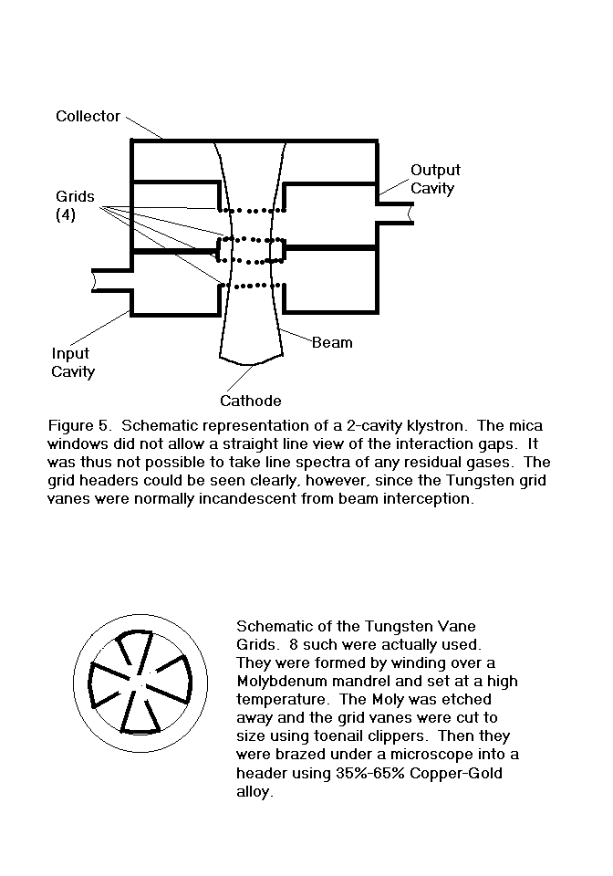
regarding a small 2-cavity klystron with mica windows.
This tube had been in production for many years with a very high
yield, roughly 90% of starts being shipped with very few returns from the
field. The yield had suddenly
dropped to roughly 60%. The
rejects suffered from power degradation over time apparently due to the
formation of a copper film over the output window.
Gas was somehow suspected as the root cause.
These tubes had no grid and no repeller, so it was not possible to
connect the electrodes as a triode to measure ion current, nor were the
gaps within direct line of sight through the transparent windows.
It was, however, possible to see two of the headers which supported
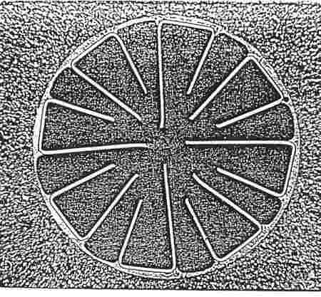
tungsten vane grids, as indicated in Figure 5.
Looking into either window with the beam on, it was apparent that
the grids were incandescent and the entire inside of each cavity was
brightly illuminated. It
would have been difficult if not impossible to observe low level spectral
lines in this background of white radiation without some kind of phase
sensitive tagging and a reduced duty cycle.
Metallographic sections through the grid vanes during autopsy
showed clear evidence of melting, de-lamination, and grain growth.
See Appendix I. The
tungsten ribbon from which the grids were made was first wrapped around a
molybdenum mandrel of the desired cross section and set in a high
temperature furnace. The
mandrel was then removed by etching in an acid bath. The
individual grid vanes were then cut from the set ribbon, by hand under the
microscope, using toe nail clippers.
The grid was then assembled into the header, by hand under the
microscope, using an alignment jig. The
vanes were then brazed to the header, under the microscope, by rf
induction in a hydrogen atmosphere using 35-65 Gold-Copper alloy.
A substantial degree of operator skill was required at every step
and essentially all of the new grids looked perfect to both the skilled
and unskilled eye. Nevertheless,
some grids melted and gave off copper vapor while others did not.
Thermal analysis failed to disclose any plausible scenario by which
beam interception or ion effects could account for the temperatures which
were obviously being encountered here.
I was forced to speculate that de-lamination of the tungsten vanes
was somehow at the bottom of the problem.
Pure drawn tungsten wire, which melts at roughly 3500 DgC, is made
by repeated drawing and annealing starting with a billet originally made
from tungsten powder scintered under pressure at roughly half the melting
temperature. Ribbon is then made by rolling the hot wire.
The end product is like a bundle of long fibers more or less
loosely bonded to each other, more or less anisotropic and prone to
de-laminate when subjected to repeated thermal or mechanical stress.
The thermal conductivity in the direction of the fibers is high,
but goes to near zero normal to the grain when the bonds between adjacent
fibers is ruptured. Even at
melting temperatures, radiation cannot account for more than a fraction of
the heat dissipation in this case so most of the power due to beam
interception had to be conducted to the header or carried off as the heat
of vaporization. My guess was
that de-lamination created a barrier to normal heat flow and resulted in
the high temperatures observed.
The puzzle was why some tubes had super hot grids and some did not
and why the sudden onset of the problem in a large fraction of the
production. Metallographic
sections of new grids did not show de-lamination while all of the grids
from failed tubes did. Moreover,
one normal working tube on life test was sacrificed and significant
de-lamination was evident in its grids as well.
The stock of tungsten ribbon became suspect and was subjected to
random sampling while the gas connection was still considered a possible
factor. Nothing was ever
found to indicate a detectable difference in the raw ribbon stock and we
were left with the general impression that all of it was subject to
de-lamination under severe repetitive thermal and/or mechanical stress.
Some years later, however, a colleague at another company devised a
high volume inspection scheme using induced eddy currents which seemed to
detect precursors to de-lamination in tungsten ribbon.
De-lamination can be prevented by the addition of 1% to 3% of
rhenium to the original billet, but the resultant properties, specifically
the electrical conductivity, are not identical to those of pure tungsten.
De-lamination can also be aggravated by the mechanical shock of
cutting with wire cutters or toe nail clippers.
This can be avoided by EDM or laser cutting.
Although it was not possible to focus directly into either gap, I
went about assembling equipment to try and detect scattered spectral lines
under pulsed conditions and reduced power to minimize the noise from hot
body radiation. One
day, while looking through a microscope hoping to see some color due to
ions, I saw a bright green flash at the instant of turn-on which could not
be replicated. Having no idea
what might be responsible for this, I went ahead and assembled a phase
locked detection system to separate spectral lines from the black body
radiation and was able to detect some very weak hydrogen lines, but I
never thought residual gas levels could explain or contribute
significantly to the basic yield problem.
The green flash was not seen again and remained a mystery until it
occurred to me that it might have been due to the ionization of barium
which had accumulated over time on the grids and been evaporated when the
grids were heated. A dozen
years earlier, our cathode guru had described to me an experiment he was
doing to measure the rate of evolution of barium from an oxide cathode.
He was using a quartz crystal behind a shutter to collect
condensible material coming off the face of an oxide cathode, primarily
barium. Then, using the quartz crystal to control the frequency of an
oscillator, he was able to watch the frequency shift and relate that to
the increased mass on the crystal. I
increased the heater voltage on one of my test vehicles and left it alone
for a week or so with no beam voltage applied.
When I turned the beam voltage on, I saw the green flash again.
Setting the spectrometer to the wavelength of the principle barium
line in the green part of the spectrum, I was able to verify my
speculation. Once I knew what
to look for, I could monitor the buildup of barium, as well as calcium and
strontium which were also active ingredients in the cathode, using much
shorter accumulation times. Of
course, all of this was idle indulgence since I had no reason to suspect
barium, calcium, or strontium evolution from the cathode to be significant
factors in the problem I was studying.
The
exact cause of our yield problem with overheated grids remained a mystery
for some time and I was diverted to other matters.
One of these involved consultation with a recently acquired
subsidiary in the gas chromatography business. I
soon had a portable gas chromatograph on a tea wagon and a need for test
samples to study the operation of this instrument.
The atmospheres in brazing furnaces, bell jars, TIG welding hoses,
and so on were handy sources and it soon became evident that these
atmospheres were not necessarily what people thought they were.
Contamination from leaks in supply lines was widespread, but unless
the consequences became catastrophic these were usually ignored.
One exception stands out... a TIG welder who told me he could tell
when his hoses needed replacement by the appearance of the weld.
Eventually I got around to sampling the atmospheres in the three
stations used to braze tungsten vane grids into headers and found that one
of them had a severe leak. The concentration of O2 in this one was roughly 100 ppm while
the O2 concentration in the other two was roughly 10 ppm. My guess is that this high concentration of O2 was not
sufficient to support an explosion, but was sufficient to prevent adequate
wetting of the tungsten ribbon by the liquid braze alloy.
I can speculate further that the liquid alloy might very well
permeate incipient fractures in the ribbon and provide the heat path which
would otherwise be missing if the fractures were left open. New orders for the products involved were on the decline and
rigid configuration controls were in force for the current production to
such a degree that these questions were irrelevant and no resources were
made available to look into them. [1]
A REVIEW OF THE THEORY OF OUTGASSING AND PERMEATION OF THE VACUUM
WALL Appendix I. Varian Associates TDM-57 August, 1969 by Rene
Rogers [2]
ELECTRON BEAM PUMPING OF RESIDUAL GASES Course notes for a
seminar given at Teledyne MEC, 1982 by Rene Rogers [3] During the course of testing one of the early WBKPA's,
the ion pump behaved erratically and the gun was connected as a triode
in order to get an independent measurement of the internal pressure.
The anode voltage had to be biased between 6 and 10 volts
negative with respect to the cathode before ion current could be
detected. This indicated
that a semi-insulating film, most likely of the kind described here,
had formed on the anode. [4]
VIRTUAL
LEAKS AND OUTGASSING THE REGION BETWEEN CLOSELY FITTING PLATES by
R. Rogers, internal memo TMEC 1982.
The instantaneous rebound model for capillary diffusion above
400 DgC with binding energies less than 2 ev is very appealing and gas
particles on the surface which can survive an overnight bakeout above
this temperature will probably stay put for 109 years at
100 DgC. Contrary to the
popular lore regarding "virtual leaks", I find it difficult,
if not impossible, to construct a scenario in which gas particles (as
distinguished from finger cots, mouse droppings, electroplating salts,
or tobacco products) trapped in a chamber separated from the rest of a
vacuum tube by a finite capillary or close fitting surfaces can
survive bakeout and still bleed out to cause trouble during an
extended shelf life at room temperature.
The interstitial reservoir between the atoms of the vacuum wall
and the torturous statistics of diffusion in solids is another matter.
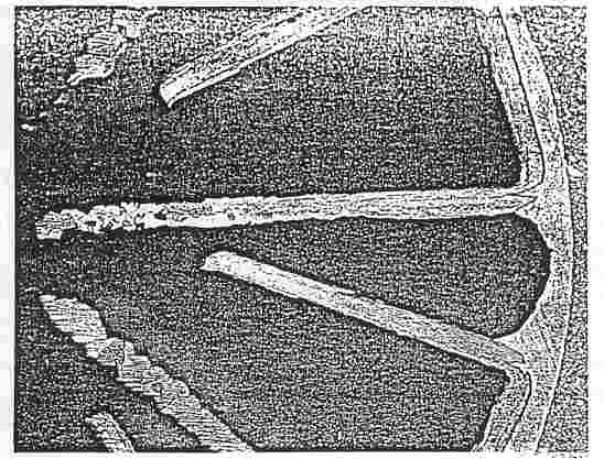
New Tungsten Vane Grid brazed into header using 35-65 Copper-Gold alloy. Note the effect of trimming the ends with a toenail clipper.
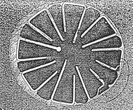
Tungsten vane grid from a klystron in autopsy after several hundred hours of operation. Compare with a new grid and note that most of the vanes have grown in width while some show clear signs of delamination.. The ruptures evident at 5 O’clock were made during polishing and are due to a void in the potting compound. Note also that one vane was melted at the tip.
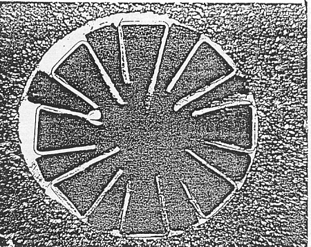
Tungsten vane grid showing delamination before melting at the tip. There is also a lot of thickening and delamination evident in other vanes. It is not clear why the vanes are not centered in the header or why the braze alloy buildup is as shown.
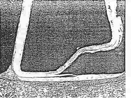
Close-up of the rupture seen in another view. This artifact was created during preparation and is due to a void in the potting compound. This picture clearly shows delamination of the vane adjacent to the header. This strongly suggests a loss of thermal contact from the vane to the header
Sorry about the quality, but in the original polished section we can clearly see some single crystal grain growth in the tungsten. The vanes were very hot, but not yet to the melting point. Note also the rupture at the base of the vanes where the tape was bent very sharply before being set at high temperature on a molybdenum mandrel. Note also the wetting and penetration of the braze alloy into these ruptures
The issue of Tungsten delamination came up again
after I joined Teledyne MEC. Helix
TWTs were, on rare occasions, returned from the customer on warranty
and “open helix” was noted on the documentation of failure
records. This failure
mode was rare and little effort was made to get to the bottom of it.
I told several people of my experience with Tungsten vane grids
at Varian and they replied with anecdotes of their own, but little was
done by way of investigation for quite a while.
I can’t say what happened to bring about the pictures on the
next page, but something did… perhaps a rash of “open helix”
diagnoses. As
background, I note that Varian had a full time team of two people who
did little except to conduct autopsies on tubes that had failed in one
way or another. It
was routine to cast the tube or the failed part in a hard clear resin
and then make polished cross sections.
These revealed a multitude of sins when examined under the
microscope. TMEC had long
since abandoned this expensive effort and foolishly relied instead on
an outside vendor for polished sections.
This was so cumbersome and unwieldy that few people bothered at
all. Perhaps partly as a
result of my continuous harping and proselytizing on the subject, TMEC
finally hired a man skilled in these arts.
I think he was kept busy all or most of the time.
The
helix-to-coax connections were made by “laser welding”…
really laser brazing using Platinum as filler.
A Molybdenum center conductor was brought to bear on the
Tungsten tape under slight pressure with a thin tab of pure Platinum
between them. Then,
in a Hydrogen atmosphere, a high power laser beam was used to melt the
Platinum. This is a very
tricky operation requiring the utmost skill.
It is easy to have so much power in the laser beam that all of
the energy goes to evaporate metal and no melting occurs. It is also easy to get a junction that looks good to the eye,
but a cross section would show that only a very thin surface had been
wet and below the surface there was no contact at all.
The TWT output power can be so high that this surface film will
be melted and an “open helix” will result.
It is also possible to have a situation where the Tungsten
delaminates and leaves part of the tape Platinum brazed to the
Molybdenum center conductor while the surface of the tape next to the
electron beam is floating with no heat path to a sink.
Several instances of melted Tungsten have been seen following
this scenario, but I don’t have those pictures.
In one case the Tungsten split extended almost a half turn of
the helix and there is anecdotal evidence that some resonant heating
of the tape has been seen.
This would surely happen if the split extended for ¼ of a
wavelength. In response to
this mounting evidence, John Wurr (Sr. Project Engr) contrived an
elegant experiment to inspect incoming Tungsten tape stock. He arranged a pair of coils inductively coupled to each other
while the Tungsten ribbon was passed from spool to spool between them.
One coil was driven by an audio frequency current while the
second coil detected the flux from the first coil including the effect
of any eddy currents in the tape.
A recording of the signal at the terminals of the second coil
clearly showed any variation in the lateral electrical conductivity of
the tape. Some sections
of the tape showed a quite uniform pattern while other sections showed
a great variation. These
signals were then correlated to latent delaminations.
John went to the supplier of the tape and tried to negotiate a
quality control effort on their part, but they told him to get lost.
His alternative was to buy his tape from a non-existent
competitor. One
proposed solution to this problem is to add 3% Rhenium to the
Tungsten. The objection
is the higher resistivity of this alloy, but a 2nd opinion
holds that the roughness of pure Tungsten is a worse factor while W-Rh
will take an electrolytic mirror polish and more than overcome this
shortcoming. The jury is
still out so far as I can learn. Sorry for the quality of the pictures… copies of copies, etc.
|
|||