| THE
BOXCAR DIODE BRIDGE CIRCUIT ---- recollections of Rene M. Rogers (c) |
|
In
around 1963-64 there was a project in Central Research at Varian to study
the photoemission spectra of certain gases that were ionized by short
intense pulses of current and/or light of one kind or another.
It fell my lot to design and construct
the necessary instrumentation to process the output of a
photomultiplier tube and present it in some suitable form.
The direct approach, feeding the signal from the PM to an
oscilloscope, was somehow inadequate.
My recollection is that the frequency response of the cheap
oscilloscope was inadequate. I
consulted Dick Whitehorn, a general expert in all things electronic, and
he suggested The Boxcar diode bridge.
I had never heard of it before and asked him how the name was
derived. He said that he
learned about the device when he was working with the RADAR group at MIT
during WWII and the name had been established by this time.
In some way he could not describe, the output of the device, when
displayed on an oscilloscope, created a sequence of blocks moving across
the screen reminding some imaginative person of a string of boxcars moving
across the countryside. Whatever
the application in those days, the device was ideal for my needs.
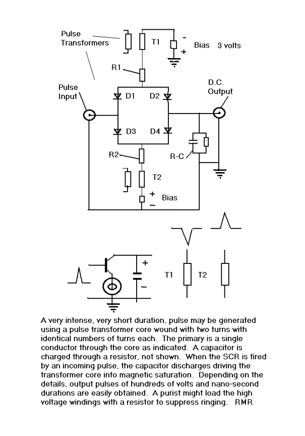
The operation is not hard to understand.
In the quiescent state, all 4 diodes are back-biased.
Suppose that the voltage at the Pulse Input port is zero, at ground
potential. When the SCR
switch is fired, a short duration pulse appears equally across the output
of each of the pulse transformers in such polarity as to overcome the bias
voltages and, if all 4 diodes have identical characteristics, equal
currents will flow in each. The
current pulse through diode D2 will charge the capacitor C + to –
referred to Ground. The current through D4 will charge the capacitor C – to +.
The net charge on C will thus be zero if the pulse voltages are
equal, if R1 = R2, and the diodes are all the same.
Suppose that we apply +1 volt DC to the Pulse Input port.
Now, when the SCR fires and pulse voltages are applied, D1 will be
cut off and D3 will conduct before D4.
The voltage from T2 will be dropped across the resistor R2 and
little or no current will flow through D4.
D2 will conduct while D1 will not and a small net charge will be
put on the capacitor C, + to – referred to ground.
Depending on the R-C time constant and the values of R1 = R2 and
the pulse voltage, the charge on C will continue to build up with each
pulse until the voltage across C is the same as the voltage at the Pulse
Input port and the bridge comes into balance again.
The limiting voltage on C is thus the value of the voltage at the
Input port during the time that the
pulse voltage is on. If
the pulse voltage, sometimes called the sampling voltage, is of much
shorter time duration than the pulse voltage at the input port, and if the
input pulse is repeated indefinitely, a quasi- D.C. voltage at the Output
port will replicate the input pulse voltage during
the time of the sampling voltage.
The entire input voltage pulse can be displayed in quasi DC form by
scanning the time of the firing of the SCR across the duration of the
input pulse. If, as often
happens, the input pulse includes a noise component, this sampling method
results in a replication of the average value of the input pulse. I
have had several occasions over the years to need, want, or recall this
device and have yet to meet anyone expert in electronics who has ever
heard of “The Boxcar” or “The Diode Bridge”.
I doubt that such a useful idea could be lost forever, but then
stranger things have happened.
Maybe this is why we keep museums.
RENE
|

