Aug. 9, 1954 Broadcasting-Telecasting
Aug. 9, 1954 Broadcasting-Telecasting
FEATURES
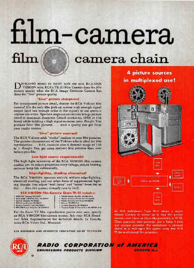
• High signal to noise ratio-l00
to 1 in the final. picture
• Aperture response correction
• Excellent resolution-l00% at
350 lines
• Low light source requirement
• Shading controls are not necessary
• Wide film reproduction range
and latitude offers possibilities
for "unattended operation"
• Small in size; compact in design
• May be mounted directly to
projectors or multiplexed
|
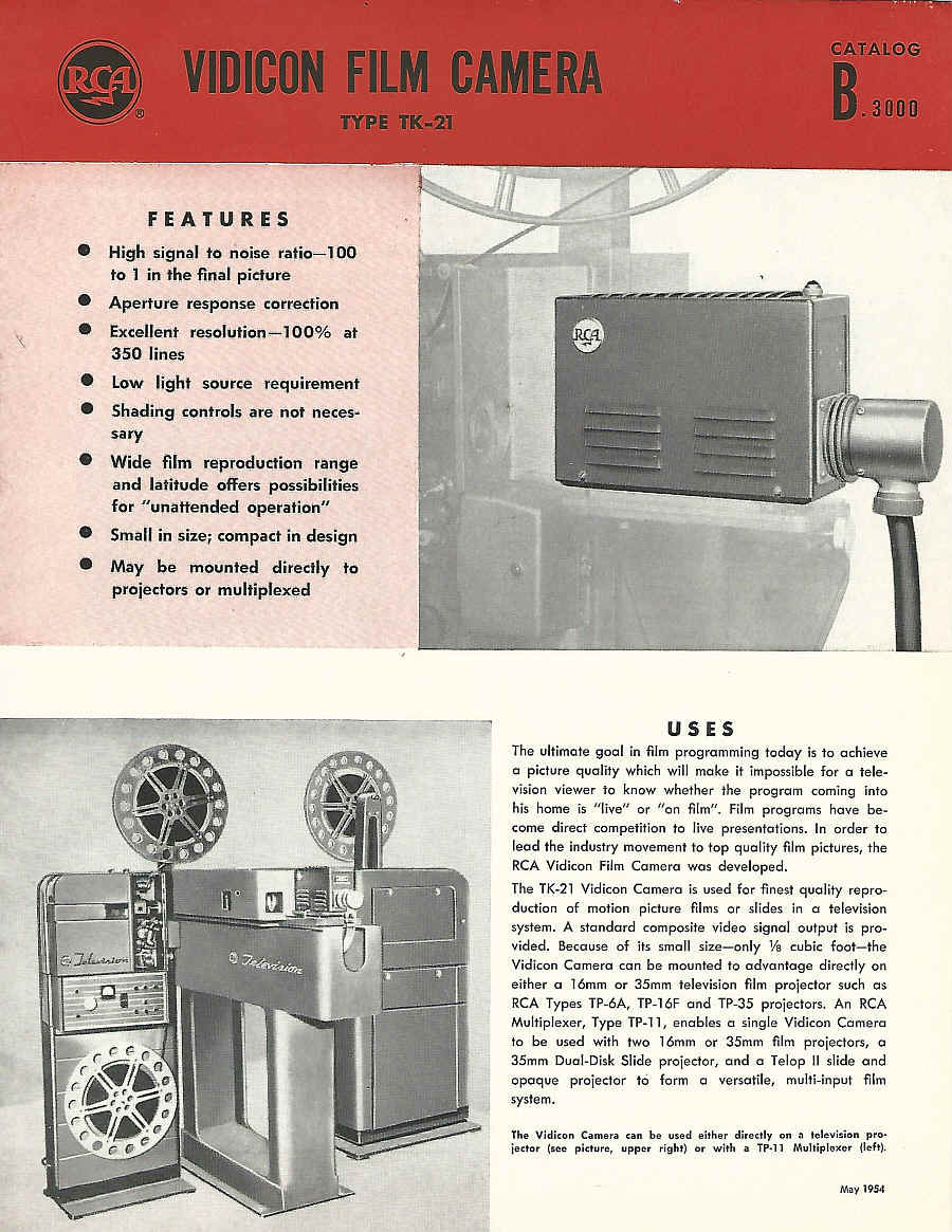
USES
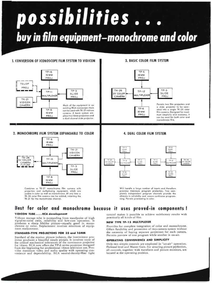
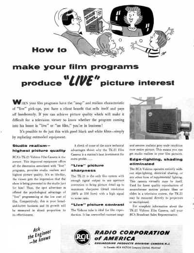
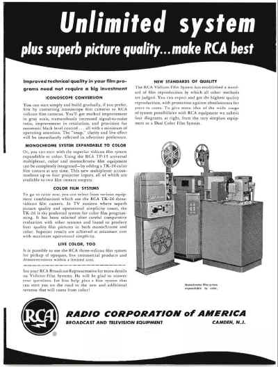
The ultimate goal in film programming today is to achieve a picture quality which will make it impossible for a television viewer to know whether the program coming into
his home is "live" or "on film". Film programs have become direct competition to live presentations. In order to
lead the industry movement to top quality film pictures, the RCA Vidicon Film Camera was developed.
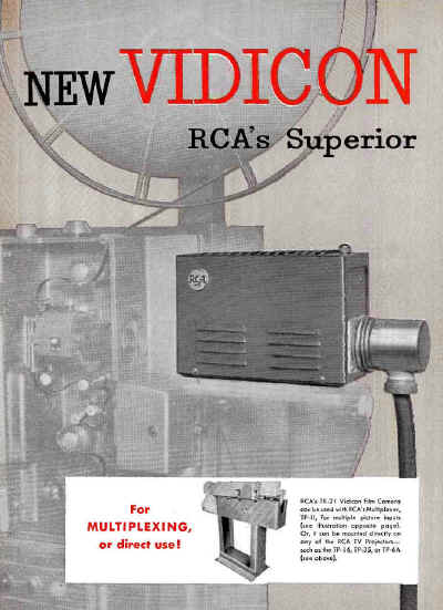
The TK-21 Vidicon Camera is used for finest quality reproduction of motion picture films or slides in a television
system. A standard composite video signal output is provided. Because of its small size-only Va cubic foot-the
Vidicon Camera can be mounted to advantage directly on either a 16mm or 35mm television film projector such as
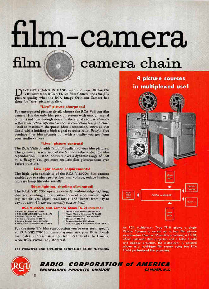
RCA Types TP-6A TP-16F and TP-35 projectors. An RCA Multiplexer, Type
TP-ll, enables a single Vidicon Camera to be used with two 16mm or 35mm film projectors, a
35mm Dual-Disk Slide projector, and a Telop II slide and opaque projector to form a versatile,
multi-input film system.
The Vidicon Camera can be used either directly on a television projector (see picture, upper right) or with a
TP·ll Multiplexer (left),
Mav 1954
|
DESCRIPTION
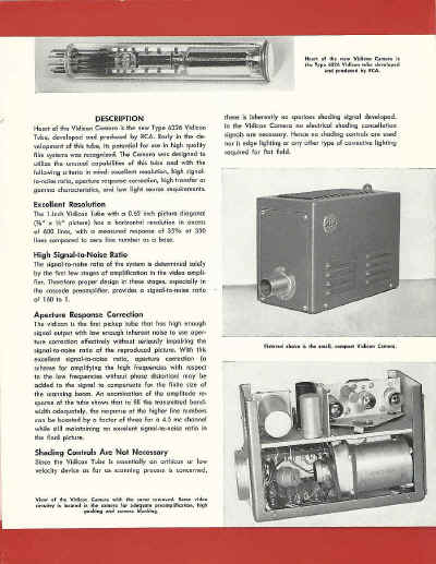
Heart of the Vidicon Camera is the new Type 6326 Vidicon Tube, developed and produced by RCA. Early in the development of this tube, its potential for use in high quality
film systems was recognized. The Camera was designed to utilize the unusual capabilities of this tube and with the
following criteria in mind: excellent resolution, high signalto-noise ratio, aperture response correction, high transfer or
gamma characteristics, and low light source requirements.
Excellent Resolution
The 1-inch Vidicon Tube with a 0.62 inch picture diagonal (3fs" x 112" picture) has a horizontal resolution in excess
of 600 lines, with a measured response of 35% at 350 lines compared to zero line number as a base.
High Signal-to-Noise Ratio
The signal-to-noise ratio of the system is determined solely by the first few stages of amplification in the video amplifier. Therefore proper design in these stages, especially in
the cascode preamplifier, provides a signal-to-noise ratio of 160 to 1.
|
Aperture Response Correction
The vidicon is the first pickup tube that has high enough signal output with low enough inherent noise to use aperture correction effectively without seriously impairing the
signal-to-noise ratio of the reproduced picture. With this
excellent signal-to-noise ratio, aperture correction (a scheme for amplifying the high frequencies with respect
to the low frequencies without phase distortion) may be added to the signal to compensate for the finite size of
the scanning beam. An examination of the amplitude response of the tube shows that to fill the transmitted bandwidth adequately, the response at the higher line numbers
can be boosted by a factor of three for a 4.5 mc channel while still maintaining an
excellent signal-to-noise ratio in the final picture.
Shading Controls Are Not Necessary
Since the Vidicon Tube is essentially an orthicon or low velocity device as far as scanning process is
concerned,
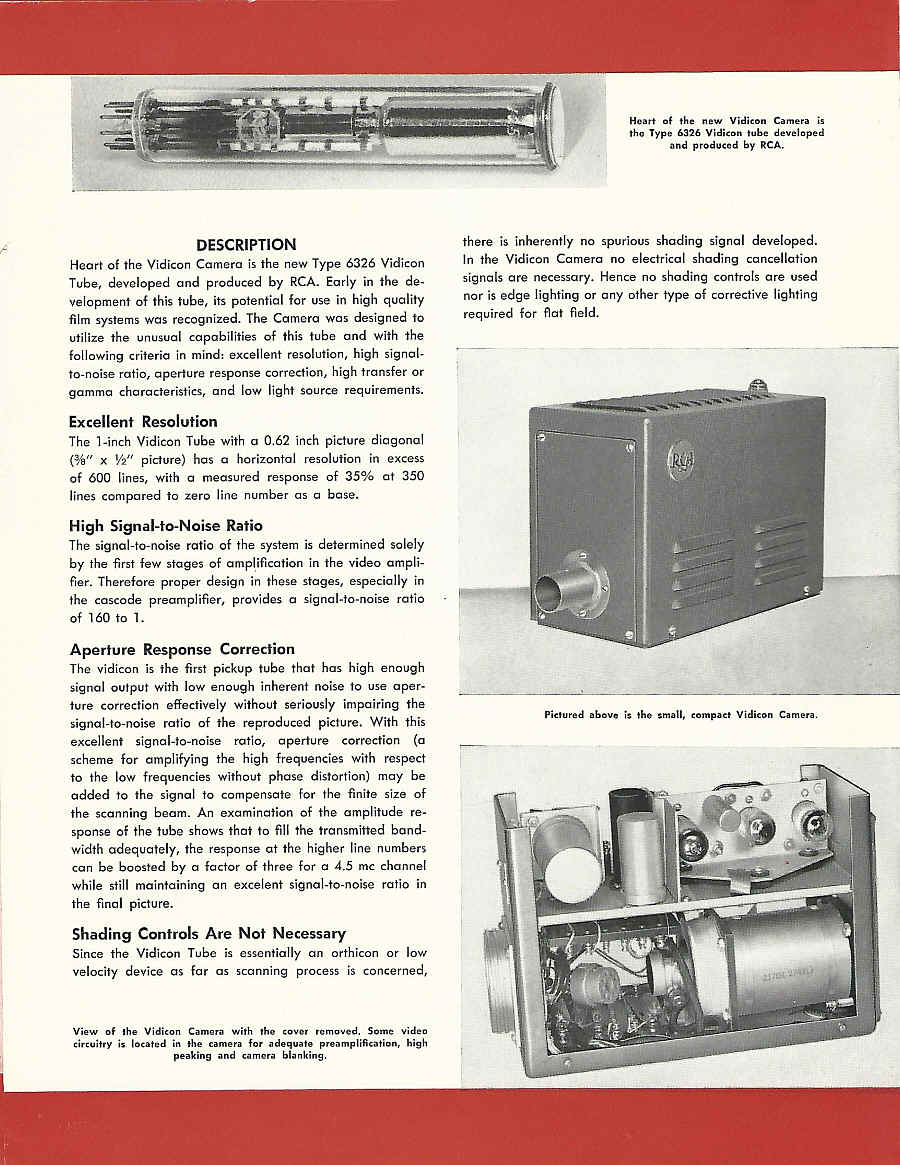
View of the Vidicon Camera with the cover removed. Some video circuitry is located in the camera for adequate
preamplification, high peaking and camera blanking.
Heart of the new Vidicon Camera is the Type 6326 Vidicon tube developed
and produced by RCA.
there is inherently no spurious shading signal developed.
In the Vidicon Camera no electrical shading cancellation signals are necessary. Hence no shading controls are used
nor is edge lighting or any other type of corrective lighting required for flat field.
Pictured above is the small, compact Vidicon Camera. |
High Transfer or Gamma Characteristic
The gamma or transfer' characteristics, which is inherent in the vidicon surface itself, has a log-log slope of 0.65 when
signal output current is plotted against light on the photoconductive surface. The slope is practically constant over
a wide film contrast range, resulting in more realistic film reproduction than ever before possible.
Low Light Source Requirements
light source requirements under favorable conditions, using commercially available lenses, average 300 foot-candles,
measured at the film gate. When the vidicon camera is mounted on a projector for direct projection, appreciably
less than full lamp voltage is needed. This lower light requirement permits reduced voltage operation of the projector lamp, thereby prolonging its life. Multiplexer operation will require more light due to multiplexing light
losses; although full voltage illumination is still in excess of operating requirements.
|
"Unattended Operation" Possibilities
The Vidicon Camera offers unusually attractive possibilities for unattended operation. Tests with a wide range of
film material have shown that it is practically unnecessary to ride video gain. Black level control is inherent in the
vidicon tube giving an absolue black reference, and shading controls are not necessary. From a day to day opera-
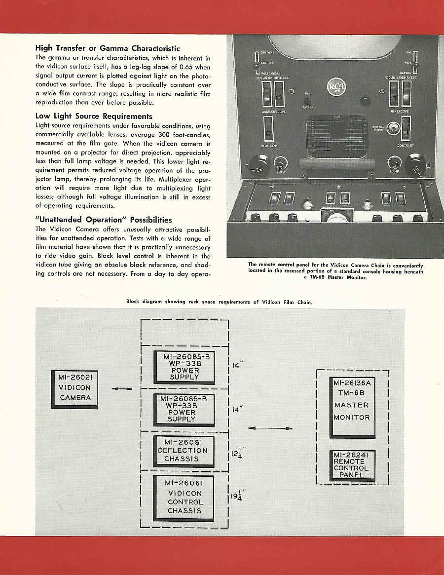
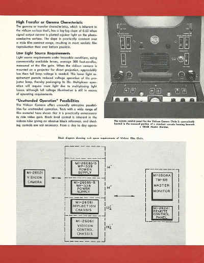
The remote control panel for the Vidicon Camera Chain is conveniently
located in the recessed portion of a standard console housing beneath
a TM·6B Master Monitor.
|
| MI-26085-B WP-33B 14 POWER
SUPPLY
MI-26081 DEFLECTION CHASSIS
MI-26061 VIDICON CONTROL CHASSIS
MI-26021 VIDICON CAMERA
MI-26136A TM-6B MASTER MONITOR
MI-26241 REMOTE CONTROL PANEL
|
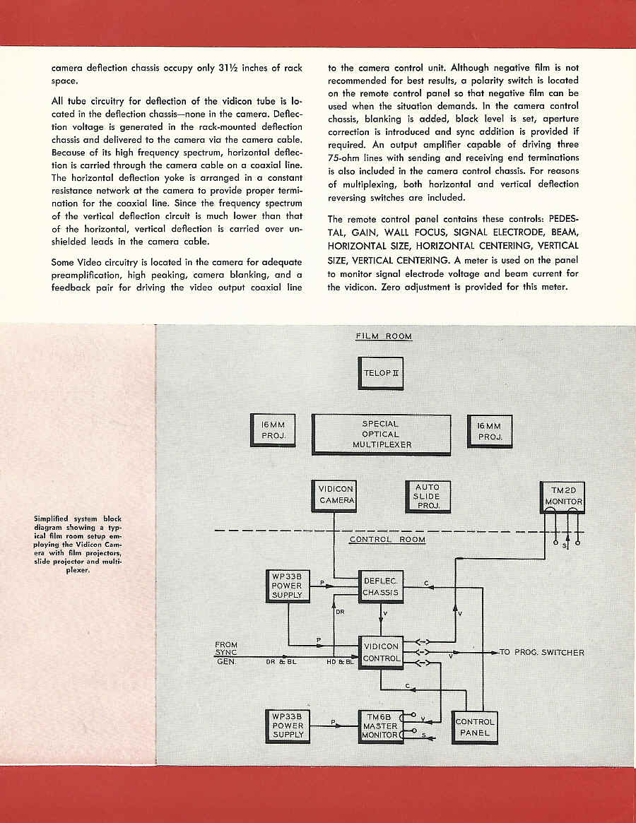
Block diagram showing rack space requirements of Vidicon Film Chain. |
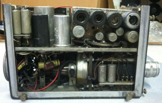
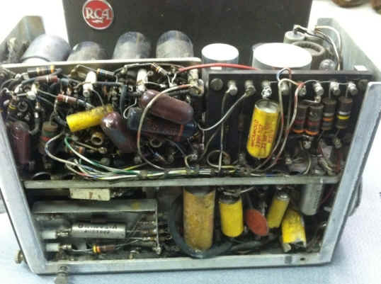
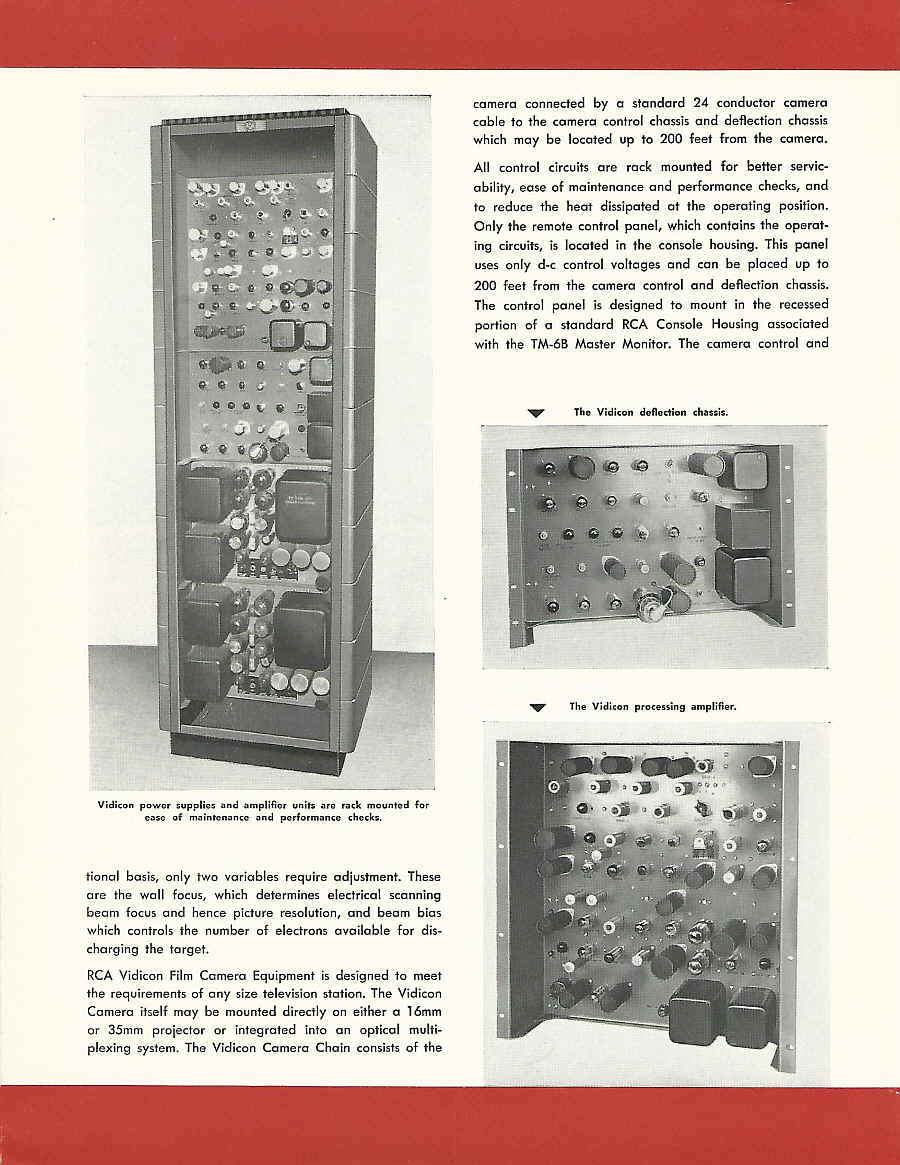
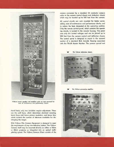
Vidicon power supplies and amplifier units are rack mounted for
ease of maintenance and performance checks.
tional basis, only two variables require adjustment. These are the wall focus, which determines electrical scanning
beam focus and hence picture resolution, and beam bias which controls the number of electrons available for discharging the target.
RCA Vidicon Film Camera Equipment is designed to meet the requirements of any size television station. The Vidicon
Camera itself may be mounted directly on either a 16mm or 35mm projector or integrated into an optical multiplexing system. The Vidicon Camera Chain consists of the
|
camera connected by a standard 24 conductor camera cable to the camera control chassis and deflection chassis
which may be located up to 200 feet from the camera.
All control circuits are rack mounted for better servicability, ease of maintenance and performance checks, and
to reduce the heat dissipated at the operating position.
Only the remote control panel, which contains the operating circuits, is located in the console housing. This panel
uses only doc control voltages and can be placed up to 200 feet from the camera control and deflection chassis.
The control panel is designed to mount in the recessed portion of a standard RCA Console Housing associated
with the TM-6B Master Monitor. The camera control and
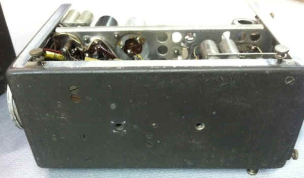
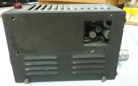
.•••. The Vidicon deflection chassis.
.•••. The Vidicon processing amplifier.
|
camera deflection chassis occupy only 31 V2 inches of rack
space.
All tube circuitry for deflection of the vidicon tube is located in the deflection chassis-none in the camera. Deflection voltage is generated in the rack-mounted deflection
chassis and delivered to the camera via the camera cable.
Because of its high frequency spectrum, horizontal deflection is carried through the camera cable on a coaxial line.
The horizontal deflection yoke is arranged in a constant resistance network at the camera to provide proper termination for the coaxial line. Since the frequency spectrum
of the vertical deflection circuit is much lower than that of the horizontal, vertical deflection is carried over unshielded leads in the camera cable.
Some Video circuitry is located in the camera for adequate preamplification, high peaking, camera blanking, and a
feedback pair for driving the video output coaxial line
|
to the camera control unit. Although negative film is not recommended for best results, a polarity switch is located
on the remote control panel so that negative film can be used when the situation demands. In the camera control
chassis, blanking is added, black level is set, aperture correction is introduced and sync addition is provided if
required. An output amplifier capable of driving three 75-ohm lines with sending and receiving end terminations
is also included in the camera control chassis. For reasons of multiplexing, both horizontal and vertical deflection
reversing switches are included.
The remote control panel contains these controls: PEDESTAL, GAIN, WALL FOCUS, SIGNAL ELECTRODE, BEAM,
HORIZONTAL SIZE, HORIZONTAL CENTERING, VERTICAL
SIZE, VERTICAL CENTERING. A meter is used on the panel
to monitor signal electrode voltage and beam current for
the vidicon. Zero adjustment is provided for this meter.
|
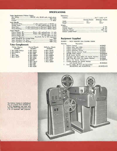
SPECIFICATIONS
Power Requirements (Vidicon Chain):
Line Rating 105-125 volts, 50/60 cycle, single phase
Power _ 535 watls
Current _ 6 amps.
I nput Signals:
Horizontal Drive .4 volts peak-to-peak at 15,750 cps
Vertical Drive .4 volts peak-to-peak at 60 cps
Mixed Sync 4 volts peak-to-peak at Standard RETMA Signal
Mixed Blanking .4 volts peak-to-peak at Standard RETMA Signal
Output Signal:
Picture Output # L .. _ Picture with optional sync, 1.4 volts
Picture Output #2 Picture with optional sync, 1.4 volts
Picture Output #3 _ 1.0 volt video-no sync
Frequency Response Essentiaily flat to 8.0 megacycles
Input Impedance for Driving Pulses High
Input Impedance for Sync __ 1000 ohms
Input Impedance for Blanking __ ._ _ 1000 ohms
Tube Complement:
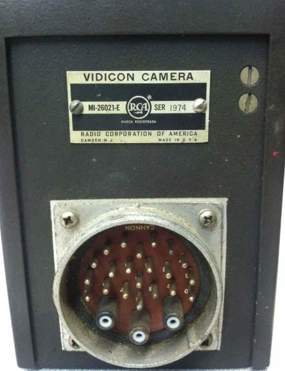
Vidicon Camera
MI-2602J
I RCA 6326 Vidicon
2 RCA 6BQ7-A
I 417-A
I RCA 12B4
I RCA 12AT7
Control Chassis
MI-2606J
I RCA 6AH6
4 RCA 6AU6
I RCA 6U8
6 RCA 6BQ7A
2 RCA 6AL5
I RCA 6AS6
2 6BX7GT
I RCA 12AT7
I RCA OB2
I RCA 6X4
I RCA 6CB6
Deflection Chassis
MI-2608J
.4 RCA 12AT7
2 RCA 12AU7
I RCA 6CD6
I RCA 6BQ7A
I RCA 6AS6
2 RCA 12AX7
I RCA 5963
I RCA 12BH7
|
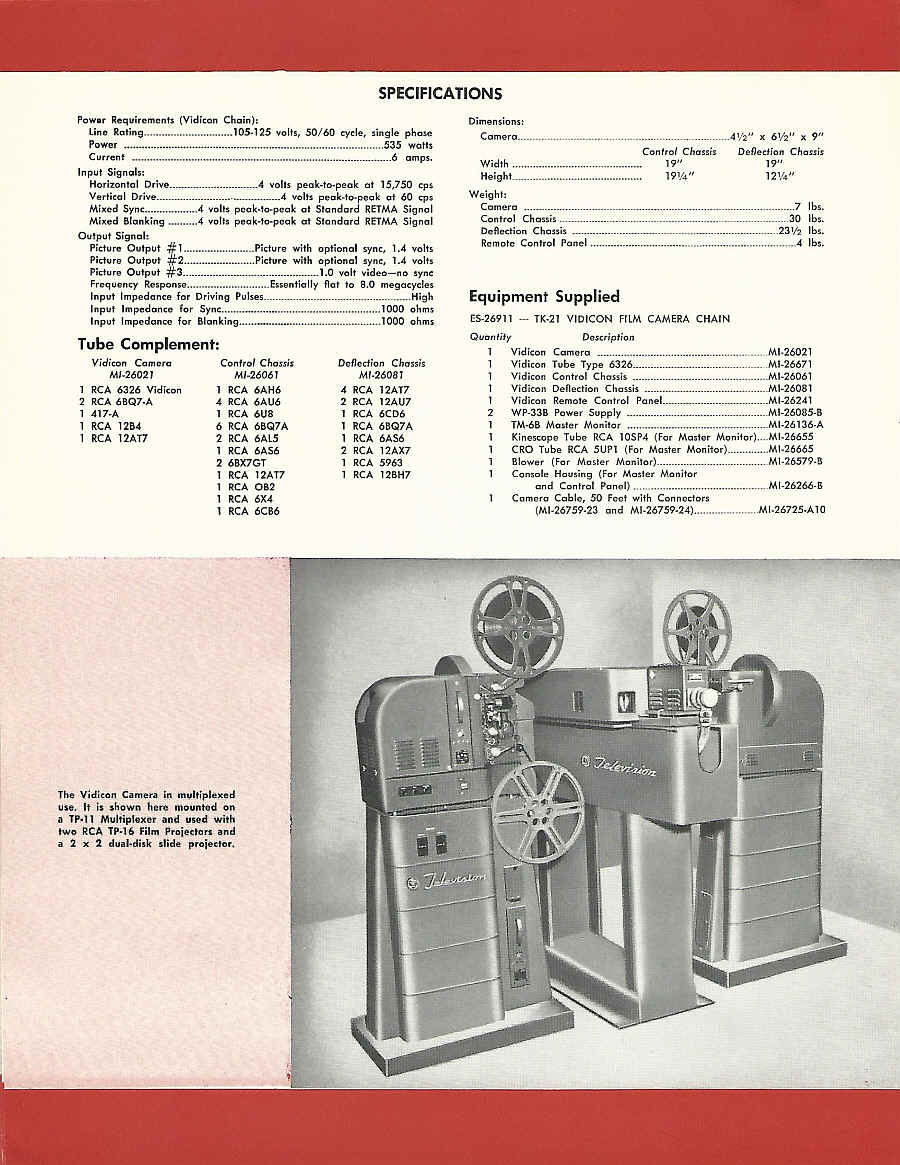
The Vidicon Camera in multiplexed
use. It is shown here mounted' on
a TP-ll Multiplexer and used with
two RCA TP-16 Film Projectors and
a 2 ·X 2 dual-disk slide projector.
Dimensions:
Camera. ._._. __ ._ __ . 41/211 X 61/2'1 X 9"
Control Chassis
Width .. __ . _ .. _ _ _ .. .__ 1911
Height............................................ 191/4"
Weight:
Camera . 7 Ibs.
Control Chassis _ 30 Ibs.
Deflection Chassis 231/2 Ibs.
Remote Control Panel .4 lbs.
Deflection Chassis
19"
121/4 "
Equipment Supplied
ES-26911 - TK-21 VIDICON fiLM CAMERA CHAIN
Quantity Description
I Vidicon Camera . MI-26021
1 Vidicon Tube Type 6326.......................... ..MI-26671
1 Vidicon Control Chassis .MI-26061
1 Vidicon Deflection Chassis .MI-26081
1 Vidicon Remote Control Panel. MI-26241
2 WP-33B Power Supply MI·26085-B
1 TM-6B Master Monitor MI-26136-A
Kinescope Tube RCA 10SP4 (for Master Monitor) MI-26655
CRO Tube RCA 5UP1 (For Master Monitor) MI-26665
Blower (For Master Monitor) MI-26579-8
Console Housing (For Master Monitor
and Control Panel) . MI-26266-B
Camera Cable, 50 Feet with Connectors
(MI-26759-23 and MI-26759-24) MI-26725-A 10 |
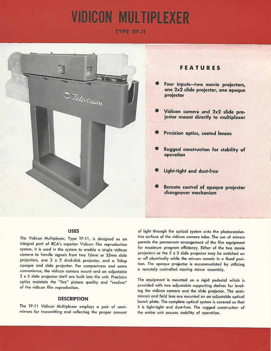
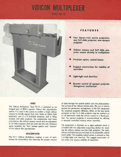
| The Vidicon Multiplexer, Type TP-ll
USES
The Vidicon Multiplexer, Type TP-ll, is designed as an integral part of
RCA's superior Vidicon film reproduction system. It is used in the system to enable a single vidicon
camera to handle signals from two 16mm or 35mm slide projectors, one 2 x 2 dual-disk projector, and a Telop
opaque and slide projector. For compactness and extra convenience, the vidicon camera mount and an adjustable
2 x 2 slide projector shelf are built into the unit. Precision optics maintain the "live" picture quality and "realism"
of the vidicon film reproduction.
DESCRIPTION
The TP-ll Vidicon Multiplexer employs a pair of semi
mirrors for transmitting and reflecting the proper amount
FEATURES
• Four inputs-two movie projectors, one 2x2 slide projector, one opaque
projector
• Vidicon camera .and 2x2 slide projector mount directly to multiplexer
• Precision optics, coated lenses
• Rugged construction for stability of
operation
• Light-tight and dust-free
• Remote control of opaque projector
changeover mechanism of light through the optical system onto the photoconductive surface of the vidicon camera tube. The use of mirrors
permits the permanent arrangement of the film equipment for maximum program efficiency. Either of the two movie
projectors or the 2 x 2 slide projector may be switched on or off electrically while the mirrors remain in a fixed position. The opaque projector is accommodated by utilizing
a remotely controlled moving mirror assembly.
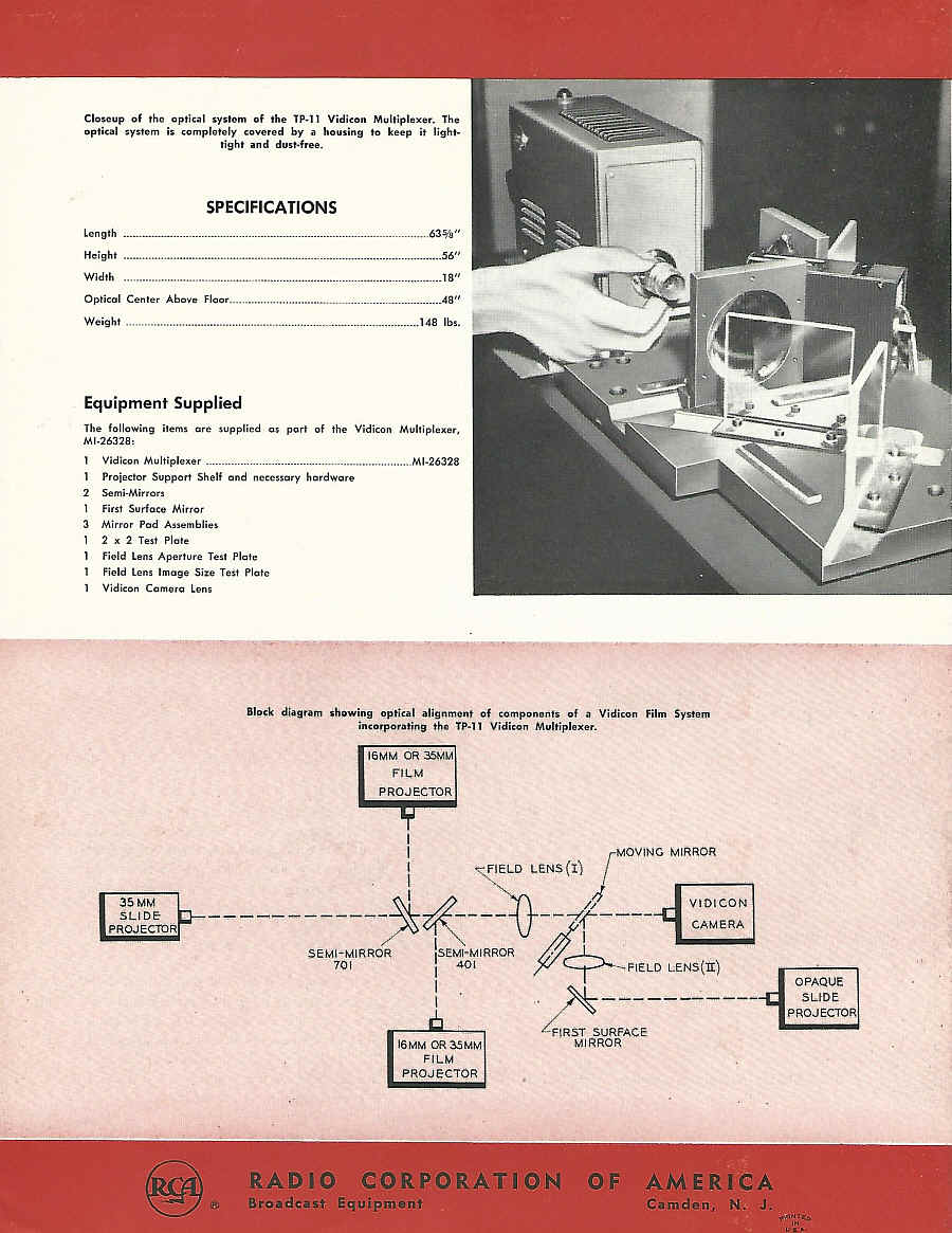
The equipment is mounted on a rigid pedestal which is provided with two adjustable supporting shelves for leveling the vidicon camera and the slide projector. The semi-mirrors and field lens are mounted on an adjustable optical
bench plate. The complete optical system is covered so that
it is light-tight and dust-free. The rugged construction of the entire unit assures stability of operation.
|
Closeup of the optical system of the TP-ll Vidicon Multiplexer. The
optical system is completely covered by a housing to keep it lighttight and dust-free.
SPECIFICATIONS
Length 635/8"
Height 56"
Width 18"
Optical Center Above Floor .48"
Weight 148 Ibs.
Equipment Supplied
The following items are supplied as part of the Vidicon Multiplexer,
MI·26328:
Vidicon Multiplexer MI·26328
Projector Support Shelf and necessary hardware
2 Semi-Mirrors
1 First Surface Mirror
3 Mirror Pad Assemblies
2 x 2 Test Plate
Field Lens Aperture Test Plate
Field Lens Image Size Test Plate
Vidicon Camera Lens
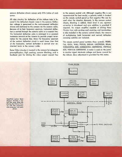
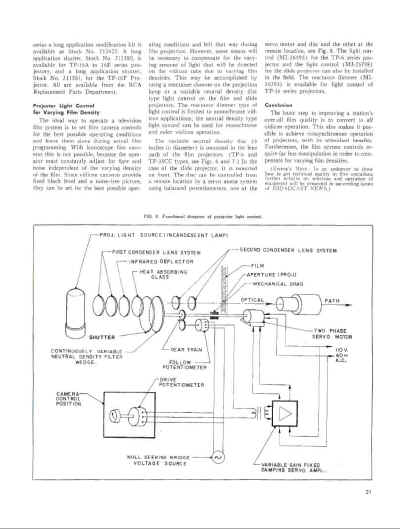
Block diagram .showing optical alignment of components of a Vidicon Film System
incorporating the TP·ll Vidicon Multiplexer.
16MM OR 35MM
FILM
PROJECTOR
I
I JMOVING MIRROR
\ ~LENS(I)
-----------~~----U-----/f---- :':~~~:
SEMI-MIRROR \SEMI-MIRROR ~.
701 I. 401 P ~---FIELD ~ENS(lt)
I . ~ .
. ~"4RST ~S:::E--------
16MM OR ~MM MIRROR
FILM
PROJECTOR
35MM
SLIDE
PROJECTOR
OPAQUE
SLIDE
PROJECTOR
'.;l |


1954
VIDICON FILM CAMERAS By H. N.
KOZANOWSKI
RCA BROADCAST NEWS Vol 78 Mar April 1954
From the Sharpe Collection at SMECC


Feb 1957 - RCA BROADCAST NEWS
Feb 1957 - RCA BROADCAST NEWS


Feb 1957 - RCA BROADCAST NEWS
Feb 1957 - RCA BROADCAST NEWS

Feb 1957 - RCA BROADCAST NEWS
Feb 1957 - RCA BROADCAST NEWS

Feb 1957 - RCA BROADCAST NEWS
Feb 1957 - RCA BROADCAST NEWS
|