|
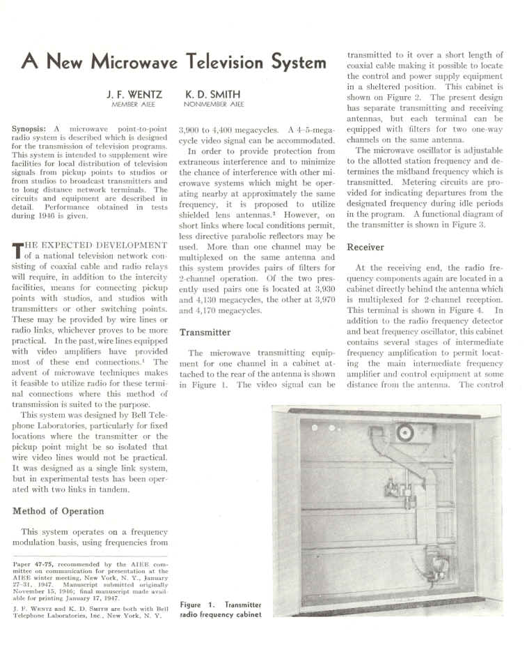
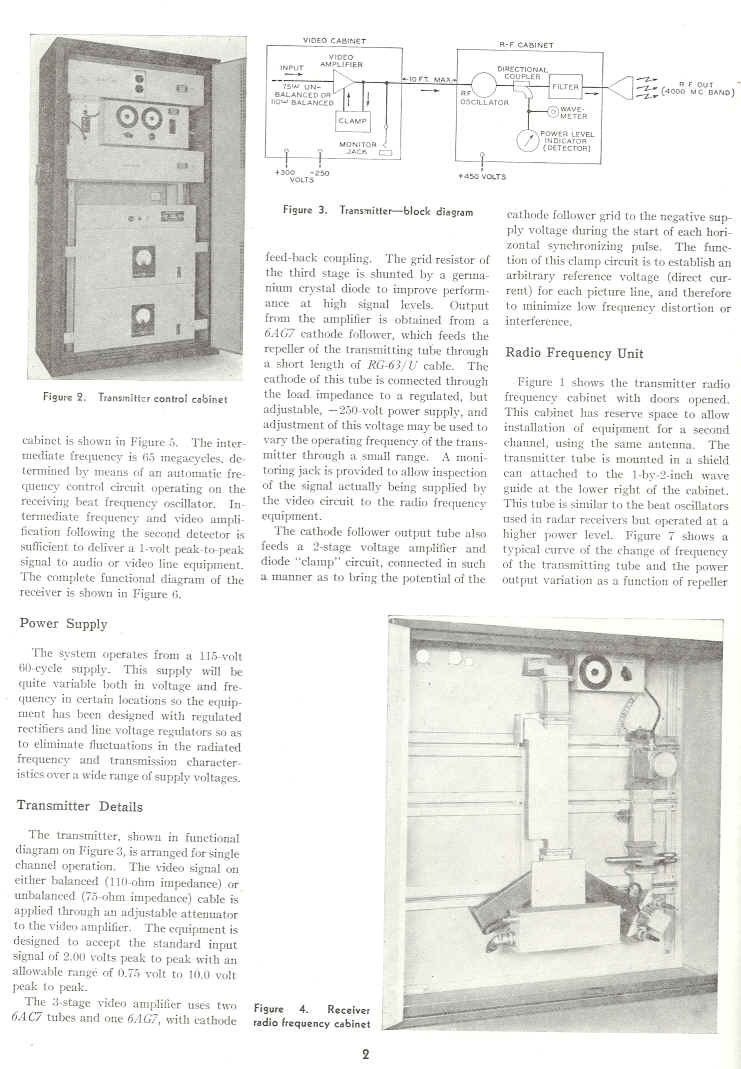
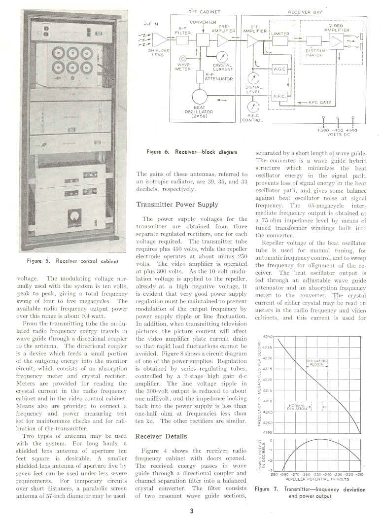
A New Microwave Television System
|
|||||||||||||||||||||||||||||||||||||||||||||||||||||||||||||||||||||||||||||||||||||||||||||||||||||||||||||||||||||||||||||||||||||||||||||||||||||||||||||||||||||||||||||||
| BELL SYSTEM PRACTICES Plant Series
J41622, ISSUE 2 AT&TCo Standard SECTION· 806-107-150 Issue 2, February 1971 AT&TCo Standard FIELD APPLICATIONS OF TE-1 AND TE-2 RADIO EQUIPMENT DESIGN REQUIREMENTS RADIO SYSTEMS Description Scope 1.01 This specification together with the supplementary information listed herein covers the equipment design requirements of typical TE radio arrangements. Supplementary information is listed covering mechanical, electrical, and transmission factors to provide a guide for selecting material for TE applications.1.03 The type TE radio system, either TE-1 or TE-2, is a frequency-modulated microwave system in the 4000-megacycle range. It is used for one-way transmission of television signals over line-of-sight paths in such applications as relaying television video signals from originating studios to commercial television transmitting stations, pick-up to local offices, or as a radio link to extend wire or radio facilities. In addition to serving as a single link, point-to-point television channel, several sets of this equipment may be used in tandem to form a relay system of more than one jump. Dual-channel operation is possible over a single link or a multiple link system. Standard RMA black and white television signals are transmitted but the accompanying audio signals are not transmitted by the TE equipment. Paralleling facilities for the sound program and for order wire must be provided. Since the operating frequencies and method of modulation are the same, TE-1 transmitting equipment may work with TE-2 receiving equipment and vice versa. On dual-channel operation, paired band-pass filters are required in both the transmitting and receiving equipment, and the same filters are used with both the TE-1 and TE-2 equipments. Both the TE-1 and TE-2 radio systems may be modified per J41608-806-107-151, J41609 Mfr Disc., J41616 Mfr Disc., and J41617 Mfr. Disc. to permit them to carry NTSC color television signals as well as monochrome signals.1.05 TE equipment may be combined in various ways and with a number of different antennas.A summation of the various combinations of TE equipment that have been made available is covered by the following table: 1.04 Separation of RF Equipment and Antenna: The TE equipment may be operated with the RF equipment close behind the antenna or with a considerable separation between the RF equipment and the antenna. To prevent incurring excessive transmission penalties when the transmitter RF equipment and antenna are separated, a radio amplifier and combinations of waveguide and coaxial cable have been made available. J41621 covers the TE-A1 radio amplifier; J68335, ED-45471-01, and ED-45472-01 cover the waveguide and coaxial cable arrangements; ED-45473-01 and ED-45474-01 cover bay layouts; while transmission considerations are covered in letters filed under AT&TCo Topical Index Code 183.4 Radio Engineering Data-Antennas and Transmission Lines. A waveguide isolator may also be employed when there is considerable separation between the TE transmitter RF equipment and the antenna.
This specification is reissued to incorporate previous appendix changes. GENERAL 1.02 1. (c) American Telephone and Telegraph Company, 1971 Printed in U.S.A. Page 1 |
|||||||||||||||||||||||||||||||||||||||||||||||||||||||||||||||||||||||||||||||||||||||||||||||||||||||||||||||||||||||||||||||||||||||||||||||||||||||||||||||||||||||||||||||
| SECTION 806-107-150
J41622, ISSUE 2
1.06 Antennas: Either shielded lens antennas or parabolic reflecting antennas may be used with TE equipment. Antenna selection and location depend on a balance among several factors such as path length, path clearance, signal-to-noise ratio permitted, interference possibilities, antenna supporting structure, etc. Portable towers of aluminum in various heights to 144 feet are available to support a parabolic antenna and associated r.f. unit as well as floor mounted frameworks. Antenna and antenna mounting arrangements for use with TE equipment are covered in J41610 whi1e avai1able towers are covered in J41618.1.07 TE-Al Radio Amplifier:. The TE-A1 radio amplifier consists of a two stage amplifier used between a TE transmitter r.f. unit and an antenna to permit separating the two without incurring excessive transmission penalties. The necessary power supplies, air supply and mountingPage 2 arrangements are integral with the amplifier. J41621 covers the ordering information for this unit and ED-45398-01 shows the equipment arrangement. 1.08 Waveguide Isolator: A waveguide isolator may be used when there is considerable separation between the TE transmitter RF equipment and-the antenna. It is recommended that a Cascade Research Corporation isolator, Uniline 38-42WE, or its equivalent, be installed in the waveguide run, as close to the RF equipment as possible, whenever waveguide runs in excess of 5 feet are used. Refer to J41608--806-107-151 and J41616-Mfr Disc.1.09 Type TE-l Radio Transmitter Equipment:The type TE-1 radio transmitter equipment (J41608) consists of three basic components; video equipment in a floor supported cabinet, r.f. equipment mounted in a cabinet, and lastly a highly directive |
|||||||||||||||||||||||||||||||||||||||||||||||||||||||||||||||||||||||||||||||||||||||||||||||||||||||||||||||||||||||||||||||||||||||||||||||||||||||||||||||||||||||||||||||
| This is taken from a catalog of BSP's that's about 20 years
old, so some of the listings may no longer be available. TE1 Microwave radio 409-100-100 Description, overall system 409-100-500 Tests TE1 Transmitter 409-110-100 Description 409-100-500 Tests TE1 Receiver 409-120-100 Description 409-120-500 Tests Terry |