| William C. Carter '38 |
|||
Datamatic 1000Written by Julian Thomas (jt at jt-mj.net)
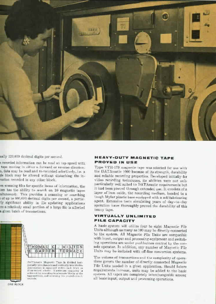
3" wide tapes with 31 data tracks across the tape; each track
held 2 words. Large reels (a bit smaller than a VW spare tire), and
physically large drives with vacuum capstans for moving the tape. Noisy
- a tape sort sounded like a convention of hippos or warthogs. Capacity
was comparable to a 2314 disk pack. 8 tapes max on the machine. Fixed
block size of 62 words. Blocks were alternately spaced on the tape so
that going forward there was a block-sized space between 'forward'
blocks for start/stop. When the tape got to the end it would reverse
direction and use the alternate blocks, so the block structure went like
this:
By convention standard "File Identification Blocks" - FIBs
were used to designate Start of File, end of file (not always used) and
End of Reserved Information (i.e. write over this when adding another
file).
Tape writing involved transferring data to the output buffer and then
issuing a write instruction, after it completed, the buffer was
prefilled with output buffer filler words (buffer fillers are described
below).
There were 2 input buffers that could be alternated (reading into one
while transferring data from the other). This was useful only if the
data was transferred and processed in chunks (smaller than the 62 word
tape block); otherwise it was simpler just to read into one buffer and
transfer the block to memory. When the buffer was empty, additional
transfers would store input buffer filler words.
Tape operations were interlocked, transfers were blocked until the
output buffer was free (or the specified input buffer was full).
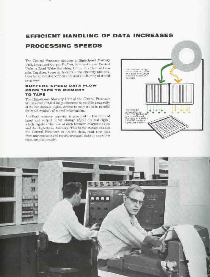
Memory was 2000 48-bit words (but see below) - core. A word was
usually an instruction (described below) or decimal (sign + 11 digits)
or alpha (8 6bit characters, altho I'm not sure the coding was identical
to IBM's. Arithmetic was decimal (8421 coded). The high order bit was a sign
(1=+); an official + was E (remember hex was B-G so E was 1101) and a
minus was 5.
Instruction format was 3 address.
The first 4 bits were sign (1 bit) and address zone bits (one for
each address), then a 2 digit op code and 3 address fields (each decimal
000-999). An address zone bit of 0 designated lower memory (000-999) 1
was 1000-1999. Certain instructions had address fields that were not
memory addresses - tape unit, count (for shifts and multiword transfers)
- not sure there was anything else.
Special addresses - 0 000 was 'void'.
Branches were by a Sequence Change (which changed the program
counter) or a subsequence call (execute one instruction without changing
the program counter); SCS (Seq Ch & SS call) did both, except that a
branch or SS call address of 0 meant 'no branch (or no SS call).
However, you could branch to 0 using a compare instruction, and there
was a "start at 0" button on the console.
Consider the following instructions:
SCS was op code 00. Branch & Return (BAR) was like SCS except
that it stored the program counter in location A - effectively this was
an SCS to the next sequential instruction. The downside of this
instructon was that for a subroutine call you either needed to know 2
addresses (where to store the return and where to start) or you needed
to subsequence to the subroutine which did its own BAR.
[I've had a nagging feeling that the D1000 had an additional
instruction that was a multi-way subseq call - SSL - shift and select -
which shifted A B places and added the single digit to C and did a
subseq call to that location. Remember that sorting was one of the
mainstays of that machine, and this was aimed at radix sorts.]
1980-1989 were normal memory locations but had various hardware
significance (a console button initiated a SS call to 1982; input buffer
fillers were sentinel ss calls to 1985 and output buffer fillers went to
1984; there may have been one for overflow).
1990-1999 were hardware registers with special significance.
Several others in there were real and had significance; one of them
must have been the program counter (which was signed + and in the B
address position). See description above of the BAR instruction. I once
put a negative number into the PC from the console. It executed one
instruction and then hung - one hand tried to go forward and the other
backwards.
There was a little-used facility - Sentinel instruction words (with a
0 sign bit). Certain operations (tape buffer transfers) would put a word
in the sentinel register if detected (remember that the buffer fillers
were sentinel subsequence calls to 1984/1985); otherwise a no-op would
go in the sentinel register, so a subsequence call to the register could
be used to differentiate. I think it had to do with a technique for
detecting buffer full/ empty conditions without having to keep count.
Instructions.
Paper tape was used for bootstrapping - the standard bootstrap was 5
words, read into 1982 and then you pushed the SS to 1982 button. Storing
into consecutive addresses was done by means of a Clary adding machine
that incremented and then set the 'write to memory' address; to do a
manual write, ISTR you set the address in the adder keyboard and then
typed in the data. Not terribly reliable; I remember that someone once
built a 'clary adder simulator' box.
I used the 2 bit shift and the decimal add instruction as the basis
for doing binary addition (and eventually an H800 simulator) on the
1000. Binary add done as follows:
The simulator used the first 1000 words of memory as H800 memory
(multiply was an option that took back 100 words; it used repeated
shifts and adds and was slow!). I don't remember if I did tape ops or
not - probably did mapping the h800 variable length blocks into 1 or
more D1000 62 word blocks (maybe there was a flag word/block size
indicator in the front of each block??). Obviously I didn't do any of
the multi programming stuff - there was just one control group, just one
set of registers.
I also coordinated the building of a cross assembler (DASH) that ran
on the D1000 and produced H800 object code. Unlike classical assemblers
that built symbol tables in memory on pass 1 and created object code on
pass 2, this one used 3 oasses plus 2 tape sorts. pass 1 generated
symbol definitions (defs) and references (refs) to tape as 3word items;
symbol; type (def or ref) and sequence number (in the source stream),
and also did error checking and parsing of the source; the intermediate
data was written on tape as 15word items and used as input to pass 5.
The tape with the 3word items was sorted on symbol value and then type
of use (def before ref). Pass 3 read the defs and refs and plugged the
definitions into the refs which were then written back out to tape; this
was where duplicate defs and unassigned symbols were detected (special
output 3 word items were generated for these); the resulting 3 word
items were again sorted - into the original order and pass 5 merged this
with the 15word items from pass 1, creating the object code and a
listing tape.
See also Martin H. Weik, "A Third Survey of Domestic Electronic Digital Computing Systems," Ballistic Research Laboratories, Report No. 1115, March 1961 at ed-thelen.org J. Ernest Smith, "A New Large-Scale Data Handling System, DATAmatic 1000," Proc. Eastern Joint Computer Conference, December 1956, pp. 22-28. |
|||
|
|||