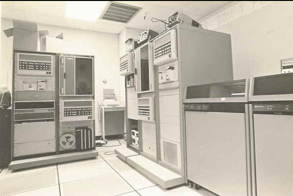

 We had a GE T-300 as a console on the MCCCD System.

|
|
HEWLETT-PACKARD JOURNAL - DOWNLOAD NICE PDF WITH GRAPHICS!Hewlett-Packard Co.
by Peter D. Dickinson
|
HEWLETT-PACKARD JOURNAL - DOWNLOAD NICE PDF WITH GRAPHICS!
Copr. 1949-1998 Hewlett-Packard Co.
Versatile Low-Cost Graphics Terminal Is Designed for Ease of Use
HP's newest computer CRT terminal combines sophisticated graphics and
alphanumeric capabilities with easy-to-use, system independent,
automatic plotting.
by Peter D. Dickinson
HIGH-PERFORMANCE GRAPHICS capabilities are made available at
relatively low cost by Hewlett-Packard's new system oriented,
generalpurpose, interactive graphics display terminal, Model 2648A
Graphics Terminal (Fig. 1). Through its microprocessor-based
architecture and raster scan technology, the 2648A Graphics Terminal
provides a powerful combination of graphics and alphanumeric
capabilities. By offering many off-line and system independent
features, it helps take the burden off both the user and the host
computer to make graphics applications more efficient and productive.
The primary purpose of a graphics terminal is to help the user process
and display graphical informa tion. Since the display is the user's
primary interface to the product, the quality of the display is
particu larly important. The 2648A uses the same high-
resolution raster scan monitor that has been used in the entire 2640A
family,1 resulting in a bright, highcontrast, easy-to-read display.
Other features made possible by the use of raster scan technology
include area shading, selective erase, interface to external monitors,
and matrix hardcopy compatibility. The 2648A's keyboard is the same as
that of other members of the 2640 family except that the numeric
keypad of other 2640 terminals is replaced by a graphics control group
that controls the graphics cur sor and display (see Fig. 2). Next to
this group is the usual display control group that controls the al
phanumeric cursor and display. Pictures can be generated manually from
the keyboard, read from optional cartridge tape units, or transmitted
to the 2648A from the host computer. Information is communicated using
ASCII charac-
Fig. 1. Model 2648 A Graphics Terminal has both graphics and
alphanumeric capabilities. Raster scan technology provides such
features as area shading, selec tive erase, and compatibility with
matrix printers. A comprehensive self test verifies operation and
helps identify the defective mod ule or component.
Printed in US A
Hewlett-Packard Company, 1978
Fig. 2. Graphics control group replaces the numeric keypad of other
2640 terminals. Each graphics key has two functions. The function on
the front of the key is accessed by pressing the SHIFT key and the
graphics key simultaneously. The keys at right control the
alphanumeric display.
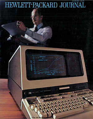
Cover: Model 2648A Graphics Terminal has both graphics and
alphanumeric capabilities. Its AUTOPLOT feature makes it easy to turn
columns of data into graphic displays like the one shown.
ters, and vectors are specified by their endpoints using either
decimal or binary format. Vector generation is accomplished digitally
by special hardware under microprocessor control. A rubber band line
(Fig. 3) can be used to facilitate manual picture gener ation. In
addition to conventional alphanumeric labeling , a special graphics
text feature allows charac-
In this Issue:
Versatile Low-Cost Graphics Terminal Is Designed for Ease of Use,
by Peter D. D i c k i n s o n p a g e Raster Scan Graphics with Zoom
and Pan, by Otakar Blazek and Michael B. R a y n h a m p a g e
Firmware Control of a MicroprocessorBased Graphics Terminal, by John
J. M o y e r p a g e 2
Add-On Digital Signal Processing Enhances the Performance of Network
and Spectrum Analyzers, by Mark D. Roos, Jacob H. Egbert, Roger P.
Oblad, and John T. Barr page 17
ters to be loaded directly into the graphics image memory. Pictures
and graphs can be labeled using graphics text in a variety of
character sizes and orientations. Two of the most interesting
features of the 2648A are zoom and pan. These features are implemented
in the terminal's hardware and are particularly useful for close
examination and editing of very highdensity displays, which are common
in applications like integrated circuit design. With a single
keystroke the display can be instantly magnified in integer steps up
to 16x (see Fig. 4). Once magnified, the display window can be moved
using the graphics cursor keys to allow close scrutiny of the entire
graphics image. If appropriate scaling is used, accurate measurements
in user units can be made directly from the display. A comprehensive
self-test feature allows the user to determine whether the terminal is
fully operational. If a failure is detected by the self test, the test
assists a service person in isolating the defective module. In many
cases the self test will actually identify the defective component.
The features of the A Graphics Terminal are a superset of those of the
2645A Display Station. In the past, many graphics applications
required two terminals, one for program preparation and one for
graphics output. The 2648A is the first graphics terminal to provide
sophisticated alphanumeric capabilities like editing, forms mode,
user-definable keys, and local mass storage. To allow maximum use of
all these features, the graphics image memory is totally independent
of the alphanumeric memory. The contents of both memories can be
viewed simultaneously or separately. In a typical application the
user's dialog with the host computer goes into the alphanumeric memory
and the graphics output into from the memory. A dot directly above
another on the screen will be offset by 720 bits, or one scan line, in
the memory. Note that moving upward on the screen corresponds to a
negative displacement. Since the raster sweeps top to bottom, the
raster origin is taken to be the upper left hand corner of the screen,
with increasing Y pointing downward. Because the conventional graphics
origin is the lower left hand corner of the screen, the graphics
screen coordinates X, Y are converted to a memory bit address by the
relation: Bit Address = (359-Y) x 720 + X The Y value is subtracted
from 359 to compensate for the shifted origin.
Display Refresh
Fig. 1. The image memory contains one bit for every point on the
display. It is organized as a linear list of 16,200 16-bit words.
The basic hardware functions of the 2648A are de scribed by the flow
chart in Fig. 3. When the power is first turned on, the microprocessor
clears the cursor, zoom, and vector flags on the GCM. The GCM then
waits for a new frame to start by looping on the vertical retrace
signal sent by the display circuitry. Since the screen dots are stored
in a linear array, displaying one horizontal line requires reading 45
words, each 16 bits wide, out of the image memory and converting them
to a serial stream directed to the display monitor. The GCM has two
buffers, A and B, each containing sixteen 12-bit words. The B buffer
can be loaded by the microprocessor via the 2648A terminal bus. When
displaying a frame, the GCM maintains three variables in the A
buffer: the read address, the word count, and the line count. The read
address is an absolute word memory address, 14 bits long and stored in
two locations, pointing to a word to be displayed. Since there are
16,200 words covering the whole screen, address zero points to the
first 16 bits in the upper left corner and address 16,199 corresponds
to the last 16 bits in the lower right corner of the
Step 5. Increment LC-LC + 1. If LC = 360 then the frame is finished.
If LCX360, set WC=0 and go to step 2.
Fig. 3. Flow chart showing the basic graphics hardware functions of
the 2648A.
screen. The word count counts the words displayed in one line. When a
count of 45 is reached, the line is complete. Similarly, when the line
count reaches 360, the frame is complete. The process of displaying a
frame then consists of the following: Step 1. While the GCM waits for
the raster to begin a new frame, it initializes the read address RA,
the word count WC, and the line count LC to zero. Step 2. Wait for a
new line to start. Step 3. Read a word at RA and serialize it.
Increment RA <- RA + 1. Step 4. Increment WC^WC + 1. If WC = 45
then proceed to step 5; otherwise go to step 3 and read another word.
The zoom feature displays image memory bits for a given magnification,
M, in the form of (M-l) x (M-l) dots, followed by one blank row and
one blank column, as shown in Fig. 4. Repeating a dot horizon tally on
the screen is achieved by dividing the shifting frequency of the
parallel-to-serial converter by M. Vertical repetition is achieved by
reading the same line M-l times. In the zoom mode, only a portion of
the image memory, as specified by the zoom starting address, is read
and displayed. Changing the zoom starting address causes the magnified
portion of the image memory to pan across the display. Since only a
portion of the image memory is being read, all mem ory rows must be
refreshed during the blank horizon tal line between magnified dots. In
the zoom mode the microprocessor outputs the zoom starting address
ZASTR, the magnification M, and the word count per line K into the
GCM's B buffer. The GCM maintains the zoom start address, the cur rent
zoom address pointing to the word being dis played, the line zoom
address indicating the first displayable word of the current line, and
the repeat count that keeps track of how many times a line has been
displayed. The word and line counts keep track of words per line and
lines per frame. In the zoom mode a frame is displayed as follows:
Step 1. While waiting for the raster to begin a new frame, the GCM
sets the current zoom ad dress ZA and the line zoom address ZAL to the
zoom start address (ZA = ZAL = ZASTR), and initializes the line count
LC=0. Step 2. Initialize the repeat count RC=0. Step 3. Initialize the
word count WC=0 and wait for raster to begin line. Step 4. Read a
memory word at the current zoom address ZA. Increment ZA < ZA + 1
and WC < WC + 1. Serialize the memory word. Step 5. Wait until the
serial conversion is complete. Step 6. If the word count WC is less
than K, the speci-
Zoom Example: Magnification = 4 MA MA+1 Bits in Memory O O O O O O
O On the Screen Visible Dot Blank Dot
Fig. 4. In zoom mode each memory bit is displaced as a square of (M -1
) x(M-1) dots, where M is the magnification. Blank lines and columns
separate the squares.
fied word count per line, then go to step 4 and read another word. If
WC=K then pro ceed to step 7. Step 7. Increment the line count LC<
LC + 1. If LC = 360 then the frame is complete. If LC<360, proceed
to step 8. Step8. Increment the repeat count RC< RC+1. If RC<M-1
(magnification- 1), then set ZA ZAL and go to step 3 to repeat the
line. If RC = M-1 then draw one blank line, update ZAL < ZAL + 45,
and set ZA <- ZAL. Then go to step 2.
Vector Algorithm
The following description of the algorithm as sumes a vector
between the points (XSTART, YSTART) and (XFINISH, YFINISH) with
absolute slope less than 45 degrees. For vectors of absolute slope
greater than 45 degrees, AX and AY are interchanged. Step 1. Compute
the initial parameters and transfer them to the graphics controller
module: AX = XFINISH - XSTART AY = YFINISH - YSTART Initial memory
address MA = 720 x (359-YSTART)+XSTART Look up the memory
displacements Ml, M2 in a table using the octant determined by
Vectors are generated by computing the memory addresses of the points
on the screen that most closely approximate the line between the
specified endpoints. An iterative algorithm is used.1'2 The memory
address for a given point is computed by adding a memory displacement
to the address of the previous point. For a vector in a given octant,
there are only two possible displacements to choose from (see Fig. 5),
and the sign of a discriminant determines which of the two to use at
each point. After the initial values have been computed, the algorithm
uses only addi tion and subtraction. The initial values for the
algorithm are computed by the microprocessor. These values include the
ini tial starting point converted from X, Y coordinates to an 18-bit
memory address, the two memory dis placements, the initial
discriminant value, two dis criminant increments, and the number of
dots to be drawn. These values are transferred to registers on the
graphics controller module, which then executes the iterative
algorithm (steps 2, 3, and 4).
Designing with 16K RAMs
The 2648A is the first HP product to use the new industry standard 1 6K RAM chips.1 The key characteristics of 1 6K RAMs that are important in this application include: high packing density, allowing the entire image memory and associated control circuitry to fit on a single plug-in printed circuit board; random access, for maximum vector drawing speed; low cost per bit because of wide industry use and multiple sourcing. The most important design objective for the image memory subsystem was high reliability. Another important consideration was that the design be compatible with the minor differences in specifications among the many vendors of the 16K RAM. Since the image memory printed circuit assembly contains high-frequency Schottky logic operating at 21 MHz in addition to the actual memory array, the first requirement was to isolate the two sections as much as possible. This was accomplished by using a memory output buffer having low input current and hysteresis to interface the memory array and display register logic. The noise generated within the memory section was minimized by using a four-layer printed circuit board with inter nal power and ground planes. Both standard tantalum and distributed ceramic capacitors are used to provide local charge storage for the memory array. All memory input lines are series terminated, since unterminated lines result in overshoot that tends to increase the error rate and can be damaging to the memory chips. The system was designed to use any 250-ns RAMs that could be qualified using HP's standard test techniques.2 One limita tion on the memory system design was that the total power dissipation had to be kept low for reliable operation at 55C ambient temperature, as called for in HP class B environmental specifications. This is normally accomplished in memory sys tem design by having the memory in low-power standby mode most of the time. This was not possible in the 2648A, because the memory is in read mode nearly all the time for the purpose of refreshing the display, so special care had to be taken to minimize the memory system power dissipation through the use of low-power logic components in all portions of the system where speed was not critical. References
1 J.E. Coeand W C. Oldham. "Enter the 16, 384-Bit RAM,"
Electronics. February 19, 1976. 2. R.J. Minicomputer
"All-Semiconductor Memory Selected for New Minicomputer
Series." Hewlett-Packard Journal, October 1974.
Fig. 5. Vectors are generated by computing the memory ad dresses of
the points on the screen that most closely approxi mate the line
between the specified endpoints. At any given raster point, there are
only two possible choices for the next raster point. If the slope of
the vector is between 0 and 45, for example, the two choices, as shown
here, are 1) over one unit, a memory displacement of +1 bit, and 2)
over one unit and up one unit, a memory displacement of -719. The sign
of a discriminant determines which to use at each point.
2648A Bus Data Sign Carry Address Blank Line
Fig. 6. display 2648A Graphics Terminal's graphics hardware consists
of the graphics display module is and the graphics controller module (GCM),
the latter shown here. The GCM is a microprogrammed machine that
determines the contents of the image memory, a separate memory from
the alphanumeric memory.
AX and AY as a key Initial discriminant D = AX + 2 AY Discriminant
increment Dl = 2 AY Discriminant increment D2 = 2 AY | - AX | Dot
count DC = | AX +1 Step 2. Write the bit at memory address MA. Step 3.
Set DC = DC - 1. If the dot count is 0, then stop, the vector is
finished. Step 4. If the discriminant D is negative, Set D = D + Dl
(update the discriminant) Set MA = MA + Ml (update the memory address)
Go to step 2. If the discriminant D is positive, Set D = D + D2
(update the discriminant) Set MA = MA + M2 (update the memory address)
Go to step 2. Communication between the microprocessor and the GCM is
via a flag. When the flag is reset the microprocessor loads the B
buffer and sets the flag, indicating that all the vector parameters
have been specified. After the vector is completed the GCM clears the
flag. Memory bits can be modified only when the beam is in horizontal
retrace, which lasts ten microseconds, long enough for the graphics
hardware to modify four dots.
Graphics Hardware Organization
The graphics controller module (GCM) is designed as a microprogrammed
machine (see Fig. 6). Its ar chitecture includes eight instruction
types and 256 words of control store, 20 bits wide. The instruction
types include four load, one store, one flag, one condi tional jump,
and one NOP instruction. The load in structions load the B hold
register with either the contents of a B buffer location or a ROM
constant, and load the A hold register with an A buffer location. This
allows adding an A buffer location and a B buffer location, or an A
buffer location and a ROM constant. The store instruction returns the
result of the addition back to the specified location in the A buffer,
or it can optionally load it into the address and/orbit registers. The
address and bit registers hold the image memory address during line
display and vector generation. The address counter, which is driven by
a 10.5MHz clock, addresses a word in the read-only mem ory. The
control word read out of ROM is loaded into the ROM output register
and decoded by the instruc tion decoder. To allow branching within the
code a conditional jump is provided. The possible jump conditions, as
determined by the condition selector, are unconditional jump, jump on
carry, sign, vertical retrace, or jump on the state of one of six
hardware flags. To save hardware, testing for zero is not done.
Instead, the appropriate variables are loaded as nega-
Otakar Blazek Oty Blazek was project leader for the 2648A. Born in
Pilsen, Czechoslovakia, he received the equivalent of an MSEE degree
in from the Techn cal Un ivers ity of Pilsen. After several years as a
production engineer in Czecho slovakia, Germany, and the U.S.A., he
earned another MSEE degree, from the University of ^California at
Berkeley, in 1971. With HP since 1972, he's contrib uted to the design
of the HP 3000 I/O system, designed the n keyboard for the 2640
family, and designed 2648A graphics hardware. Several U.S. patent
appli cations came out of the 2648A project. Oty is single and lives
in Sunnyvale, California. He speaks five languages and enjoys tennis
and skiing.
Firmware Control of a MicroprocessorBased Graphics Terminal
by John J. Moyer I HE 2648A is a microprocessor-based graphics
terminal whose operation is completely con
trolled by microcode stored in read-only memory (ROM). This firmware
is based to a large extent on
code written for the 2645A Display Station. The 2645A was designed in
a modular fashion to simplify extensions for future products. For
example, impor tant sections of the 2645A firmware were imple mented
using tables. These tables were merely ex panded to include the new
functions of the 2648A. Redefining the numeric keypad of the 5 A as
graphics function keys required changes to only one discrete keyboard
module. The firmware for the 2645A requires 22K bytes of ROM. Graphics
exten sions for the 2648A add 18K bytes. The following paragraphs
illustrate how the mi croprocessor was used in implementing several of
the graphics features. In some cases, a task is partitioned between
firmware and hardware, while in others the microprocessor interacts
with the user to make the terminal easier to use.
Vector Generation
as well as the ability to draw either white on a black background or black on a white background. To draw dotted and dashed vectors, the microprocessor can load and enable an eight-bit pattern memory on the graphics display module. Instead of drawing every dot in the vector, bits can be written or skipped over, according to the pattern (Fig. 1). The pattern can be stretched up to 16 x by a prescaler.
Cursor
The user causes the terminal to draw a vector by specifying a single endpoint. The terminal calculates the raster points that most closely approximate the straight line between the new endpoint and the pre vious endpoint. The microprocessor converts the endpoint from ASCII characters (suchas 500,250) ora more efficient packed format (which reduces the endpoint 500,250 to the characters /4':) to binary. If either endpoint of the vector is off-screen, the coordi nates of the portion of the vector that is on-screen are computed and substituted as new endpoints. The parameters required by the graphics controller mod ule (GCM), described in the article on page 6, are then computed. Next the microprocessor tests a flag on the GCM to determine whether it has finished drawing the previous vector. When the GCM is idle, the mi croprocessor transfers the vector parameters and sets a flag that tells the GCM that a new vector is ready. The microprocessor can begin processing the next endpoint while the GCM is drawing the vector. The microprocessor can set the mode in which a vector is drawn. The bits that make up a vector can be written by setting, clearing, or complementing the image memory. This gives selective erase capability,
The graphics cursor is drawn in the image memory as intersecting horizontal and vertical vectors. The microprocessor scans the graphics cursor keys to de termine where the cursor should be drawn. The start ing addresses for the two vectors are computed so the center of the cursor is in the specified position. If any part of the cursor would go off-screen, a shorter length for the appropriate vector is computed. The micro processor then loads the GCM with the two addresses and two vector lengths, and sets a flag indicating that
Graphics Self Test
Self test is an important feature in all HP terminals. It is de
signed to answer the basic question, "Does it work?" Self
test also provides valuable diagnostic information. Since the com
plexity of the new graphics hardware is comparable to the entire
digital portion of HP's first terminal, the 2640A, the addition of a
comprehensive graphics self test was particularly important. The 2648A
graphics self test consists of three tests. "Marching
Vector" Memory Test This is analogous to a "marching
1's" and "marching O's" memory test. However, unlike a
normal diagnostic, its operation can be viewed on the CRT in addition
to being tested by the graphics controller. It verifies that the
graphics vector generator operates in all four quadrants and that the
graphics memory contains 259,200 uniquely addressable bits that can be
set to a 1 or a 0. If any memory errors are discovered, they are
reported on the display. The location of the failed memory pack is
also indicated, allowing simple replacement of the socket-mounted
part. Display Test This is a visual test only, since the processor
does not have access to the 21 MHz video bit stream. First ZOOM is
tested by displaying a succession of numbers corresponding to
different zoom factors. The numbers are written in sizes that are com
plementary to the zoom factors used, and consequently should all
appear the same size on the screen. PAN is then tested by moving a
checkerboard pattern across the center of the screen past the
crosshair graphics cursor. If the pattern traverses the screen
smoothly, then virtually all the zoom and pan hardware must be
operating correctly. Alphanumeric Self Test Since the 2648A features
are a superset of the 2645A Display Terminal's features, the remainder
of the 2648A self test is identical to the 2645A self test.
Firmware-implemented graphics features are also tested here, since
part of the test checks all of the ROMs to ensure that their stored
bit patterns are intact.
Resultant Vector Scale Factor = 1 Pattern Byte
Scale Factor = 2
Fig. 1. The 2648 A Graphics Terminal uses an eight-bit pattern byte to specify dotted and dashed lines. A scale factor can be applied to stretch the pattern up to 16 x.
memory. To erase it, the identical bits are com plemented again.
Complementing a bit twice restores it to its original state.
Complementing also insures that the cursor will always be visible,
regardless of the background. However, as seen in Fig. 2, gaps will
appear in vectors intersecting the cursor when the cursor is drawn. To
remedy this, the cursor is recom plemented every frame. The resulting
cursor appears half-bright because it is only visible every other
frame, but it does not cause gaps when placed on top of other vectors.
Fig. 2. The 2648 A's graphics cursor is drawn by complement ing bits
in the image memory and is erased by recomplementing the bits (bottom
drawing). This avoids the problem shown in the top drawing, where
erasing the cursor leaves a gap in any line that intersects it.
However, drawing the cursor by complementing, as shown in the bottom
drawing, leaves a gap atan intersection with another line. To remedy
this the cursor is recomplemented every frame.
a cursor is to be generated. The GCM draws the cursor during vertical
retrace, while the display is blanked. When the cursor is moved, the
cursor at the old position is erased before a cursor is drawn at the
new position. As Fig. 2 illustrates, if a line is erased by clearing
bits in the image memory, gaps will be left in any line it intersects.
If the cursor were erased this way, large parts of the display would
be erased as the cursor moved across the screen. Consequently, the
cursor is drawn by complementing bits in the image
Zoom allows the user to select a subset of the image memory and
magnify it to fill the entire display. The center of the area to be
zoomed is selected with the graphics cursor. The microprocessor uses
the cursor coordinates and the desired magnification to deter mine the
memory address of the first bit that will be displayed in the
upper-left hand corner of the zoomed area. If this address is not on
an image memory word boundary, the number of bits in the first word
read that are not to be displayed is determined. The number of words
to be read from the image memory, which decreases as the magnification
increases, is also computed. The microprocessor loads these parameters
into the proper buffer locations on the GCM, and sets a flag
indicating that zoom mode is to be turned on. The GCM changes into or
out of zoom mode only during vertical retrace.
Graphics Text
To provide different text sizes and orientations, the microprocessor can draw dot matrix characters di rectly into the image memory. The smallest character is defined in a cell seven dots wide by ten dots high. It is generated by drawing ten vectors, each seven dots long. Before a vector is drawn, an appropriate pattern
Pattern Vector 10 Pattern V e c t o r 9 Pattern V e c t o r 8
Pattern V e c t o r 7 Pattern V e c t o r 6 Pattern V e c t o r 5
Pattern V e c t o r 4 Pattern V e c t o r s Pattern V e c t o r 2 P a
t t e r n V e c t o r 1
Fig. 3. Graphics characters are drawn as a series of adjacent vec tors,
using a different dot-dash pattern for each vector. The small est
character cell consists of ten vectors, each seven dots long.
Characters are rotated or slanted by changing the direction of the
vectors.
byte specifying the dot-dash line pattern is read by the
microprocessor from a table stored in ROM. To draw characters at
different angles, the direction in which the vectors are drawn is
changed (Fig. 3). Larger characters are generated by increasing the
size of each dot in the dot matrix representation. For example,
multiplying the vector length and pattern prescale by three and
repeating each pattern three times will draw each point in the matrix
as a three-dot-bythree-dot square. The microprocessor can also left
justify, right justify, and center strings of graphics text.
Autoplot
reset to 0. Only the relative position in the data stream is used to determine which data column a number belongs in, not the physical position on the screen. Con-
Single Character
Autoplot allows plots to be made directly from tabular data. The user enters simple parameters about the data into a menu. These menu entries tell the terminal how many columns of data there are, which column is to be used for X data and which for Y, and what the minimum and maximum values are. If tick marks are desired, the spacing between them must be given also. Using this information, the microproces sor will draw the axes and tick marks, with labels and a grid if desired, select the proper data values, scale them, and plot them. Axis generation is straightforward. The micro processor reads the values stored in the menu, checks them for possible errors, then uses them to determine where the axes and tick marks should be drawn. When generating tick mark labels, the format of the menu entry is used to determine the format of the label. If the spacing given in the menu entry has no decimal point, the tick labels are written as integers. If the menu entry contains a decimal point, the tick label is rounded to the same number of places after the decimal. When autoplot mode is turned on, the micro processor scans all incoming data one character at a time, reconstructs complete numerical values from appropriate ASCII characters, and determines which of the numbers it has built should be used for X and Y data points. The flow chart in Fig. 4 illustrates the process. The scanner starts building a number when a numeric character (0-9, +, -, or.) is detected. Suc ceeding numeric characters are concatenated onto the value being built. When a non-numeric character ar rives, the string being built is terminated. A column counter is then incremented to determine which data column the string is in. The column count is com pared with the menu fields for the X and Y data columns, and if a match is found, the string is con verted from ASCII to a floating-point representation and stored. When both X and Y values have been received, they are scaled using the values in the MIN and MAX menu fields, and plotted. When the column count exceeds the value in the NO. OF COLS, field, it is
Stop Building Number Column Count-* Column Count +1
Fig. 4. A flow chart illustrating how the autoplot scanning routine
picks out selected columns from tabular data.
sequently, data formatted for 132-column line print ers, which will be
split across two of the 2648A's 80 character lines, is correctly
scanned. Intervening text or blank lines are ignored. By entering
twice the number of data columns in the menu, every other point can be
plotted. The source of the plot data can be selected as either the
data communications module, the cartridge tapes, or the data being
displayed on the screen, which is available to the microprocessor from
the terminal's display memory.
I would like to express my appreciation to Ed Tang, Warren Leong,
George Hunt, and Rick Palm for their help in interfacing to the
existing 2645 firmware; to Pete Showman for his inputs on graphics; to
Mike Ramsay and Myron Tuttle for their Q.A. efforts; and to Greg
Garland and Bill Woo for their datacom exper tise. OS
John J. Moyer John Moyer received his BA de gree in computer science
from the University of California at Berkeley in 1975, then joined HP
to work on the graphics firmware for the 2648A. He's named as an
inventor on several patent applications re lated to the 2648A. Born in
Syra cuse, New York, John is single and now lives in Cupertino,
California. For recreation, he likes covering distance, either in the
air he's a private pilot or on the ground, with a pack on his back.
HP Model 2648A Graphics Terminal
SCREEN SIZE: 127 mm (5 inches) x 254 mm (10 in). SCREEN CAPACITY: 24
NnesxSO columns (alphanumeric); 720 dotsx360 raws (graphics).
CHARACTER GENERATION: 7x9 enhanced (alphanumeric); 9 x 15 dot
character cell; non-interlaced raster scan. CHARACTER SIZE: 2.46 mm
(.097 in) x 3.175 mm (.125 h) (alphanumeric); 5 x 7 dot character cell
(graphics). CHARACTER SET: 128 character (alphanumeric) CURSOR:
Blinking-Underline (alphanumeric); Blinking-Crosshair (graphics).
DISPLAY MODES: White on black; black on white (inverse video).
Optional halfbright, underline and blinking. REFRESH RATE: 60 Hz (50
Hz optional). TUBE PHOSPHOR: P4. IMPLOSION PROTECTION: Bonded
implosion panel. MEMORY ALPHANUMERIC: 37 lines of 80 characters (less
enhancements). GRAPHICS: 720 dots by 360 rows of displayable points.
OPTION SLOTS: 4 available. KEYBOARD: Detachable, bit pairing;
user-defined soft keys, control and editing keys; 1.2-m pad; cursor
pad; auto-repeat, n-key rollover; 1.2-m (4-foot) cable. CARTRIDGE TAPE
(option): Two mechanisms READ/WRITE SPEED: 10 ips SEARCH/REWIND SPEED:
60 ips RECORDING: 800 bpi MINI CARTRIDGE: 110-kilobyte capacity
(maximum per cartridge) DATA COMMUNICATIONS DATA RATE: 110, 150, 300.
1200, 2400, 4800, 9600 baud, and external. Switch selectable (selects
two stop bits). Operation above 2400 baud may require nulls requires
handshake protocol to insure data integrity. External clocking
requires a TTL signal 16x bps. VECTOR screen. TIME (9600 baud,
typical): 7 ms half screen; 10 ms full screen. STANDARD ASYNCHRONOUS
COMMUNICATIONS INTERFACE: EIA standard RS232C; fully compatible with
Bell 103A modems; compatible with Bell 202C/D/S/T modems. Choice of
main channel or reverse channel line turn-around for half duplex
operation. OPTIONAL COMMUNICATIONS INTERFACES (consult 3260A/B/C/D Com
munications data sheet for details) : Current loop, split speed,
custom baud rates Asynchronous Multipoint Communications Synchronous
Multipoint Communications-Bisync TRANSMISSION MODES: Full or half
duplex, asynchronous. OPERATING MODES: On-line; off-line; character,
block. PARITY: Switch selectable; even, odd, none. ENVIRONMENTAL
CONDITIONS TEMPERATURE, FREE SPACE AMBIENT: Non-Operating: -40 to +75C
(-40 to + 167F) Operating: 0 to 55C (+32 to + 13TF) TEMPERATURE, FREE
SPACE AMBIENT (TAPE): Non-Operating: -10 to 60C (-15 to + 140F)
Operating: 5 to 40C (+41 to +104F) HUMIDITY: 5 to 95% (non-condensing)
HUMIDITY (Tape): 20 to 80% (non-condensing) ALTITUDE: Non-Operating:
Sea level to 7620 metres (25,000 ft) Operating: Sea level to 4572
metres (15,000 ft) VIBRATION AND SHOCK (Type tested to qualify for
normal shipping and handling in original shipping carton):
Vibration:.37 mm (0.015") pp, 10 to 55 Hz, 3 axis Shock: 30 g, 11
ms, 1/2 sine PHYSICAL SPECIFICATIONS DISPLAY MONITOR WEIGHT: 19.6 kg
(43 pounds) KEYBOARD WEIGHT: 3.2 kg (7 pounds) DISPLAY MONITOR
DIMENSIONS: 444 mm W x 457 mm D x 324 mm H (17.5 in W x 18 in D x 13.5
in H). 648 mm D (25.5 in D) including keyboard. KEYBOARD DIMENSIONS:
444 mm W x 216 mm D x 90 mm H (17.5 in W x 8.5 n D x 3.5 in H) POWER
REQUIREMENTS INPUT VOLTAGE: 115 ( + 10%-23%) at 50/60 Hz (0.2%) 230 (
+ 10%-23%) at 50 Hz (0.2%) POWER CONSUMPTION: 115 W to 150 W max.
PRICE $7100. U.S.A.: 2648A, $5500. 2648A with cartridge tape units,
$7100. MANUFACTURING DIVISION: DATA TERMINALS DIVISION 19400 Homestead
Road Cupertino, California 95014 U.S.A.
SPECIFICATIONS
16 Copr. 1949-1998 Hewlett-Packard Co.
Add-On Digital Signal Processing Enhances the Performance of Network
and Spectrum Analyzers
Digitizing and storing the outputs of network and spectrum analyzers
enables flicker-free display of slowly swept measurements, corrections
for system errors, and direct comparisons of device performance.
Additions to the basic storage circuits achieve improved
signal-to-noise ratios and increased resolution.
by Mark D. Roos, Jacob H. Egbert, Roger P. Oblad, and John T. Barr
THE CONTINUING EVOLUTION of digital signal-processing techniques now
allows the instrument designer to add powerful capabilities that were
previously not practical because of cost. Storage of CRT displays is a
case in point. Digital storage allows the user to make swept-frequency
measurements at a slow rate, and then display the acquired data
repetitively at a fast enough rate to enable viewing the entire sweep
without annoying flicker. Another advantage of digital signal
processing and storage is the capability for applying scalar
correction factors. Commonly called normalization, the applica tion of
correction factors removes frequency-response errors that often mask
the true response when swept measurements are made with
less-than-perfect mi crowave test fixtures (Fig. 1). Normalization has
been done with computers in automatic test systems, but with the
newer, more powerful, low-cost digital cir cuits that are presently
available, this capability can now be designed into instruments used
on the bench. A third useful capability provided by digital stor age
is the retention of measurement data for compari
son with data taken later (Fig. 2). This is useful for matching
devices, or for examining characteristics by observing changes in
performance while one of the measurement parameters is varied. For
example, changes in amplifier gain compression can be moni tored as
the input signal level is varied.
An Add-on Capability
These and other capabilities have now been de signed into two new accessory instruments for use primarily with network and spectrum analyzers. The first of these, Model 8750A Storage-Normalizer (Fig. 3), accepts the X-Y outputs from a network or spectrum analyzer, samples the X-Y outputs during a single swept-frequency measurement, converts the samples to digital words, stores the words, and reads them out repetitively into a digital-to-analog con verter. The measurement data is reproduced repeti tively at a rate of 167 sweeps per second for flickerfree presentation on the analyzer's CRT. A line generator connects the data points on the display so a smooth, continuous trace is obtained. Model 8750A can store the data input of two chan-
Hewlett-Packard's implementation of IEEE Standard 488-1975.
Fig. of Model A Storage-Normalizer retains the results of dual-channel
swept-frequency or other-type measurements for flicker-free display,
normalization, and comparison. It works with suitably equipped
frequency response sets and spectrum analyzers in HP 180-series
mainframes and with the 8407 A and8410A/B Network Analyzers. It can
work with spec trum analyzers in HP 140-series mainframes with the
addition of a display monitor or oscilloscope. It also works with
other types of instrumentation.
Fig. 4. Model 8501A StorageNormalizer is optimized tor use with the
Model 8505A Network Analyzer. Among other functions, it enables
flicker-free display of slow-sweep measurements, nor malizes
measurements to remove frequency-response errors, and averages
repetitive measure ments to improve signal-to-noise ratios.
time needed for multiple-frequency go/no-go mea surements in a
production environment. Model 8501A can also store processed data from
an HP-IB system controller and convert the stored information to
analog form for display on the network analyzer's CRT. The system is
thus able to acquire data in one form and reformat it for display in
another form. For example, a swept measurement of reflection coeffi
cient can be reformatted and displayed as input im pedance magnitude
and phase angle. Model 8501 A has line generators on both the X and Y
axes, giving it full graphics capability. Under con trol of an HP-IB
system's desktop controller, the line generators can be used to trace
vectors between any two pairs of X-Y coordinates on the network
analyzer's CRT, enabling limit lines or complete graticules to be
overlaid on measured data. The sys tem controller can aid the operator
further by notify ing him by an audio or visual message when and where
measurement data exceeds limits. The 8501A also has a built-in
character generator that can be used to annotate the displays (serial
num bers, dates, etc.) and to present messages to the operator on the
network analyzer's CRT (Fig. 6). Up to 22 lines of text can be written
using the English and Greek alphabets, numbers, and a complete set of
mathematical symbols. Since the controller can also
use the 850lA's graphics capability to generate dia grams of test
connections, it is unnecessary to provide written test procedures.
Programs for long, involved test procedures can be stored on tape
cartridges and entered into the controller as required. An option
enables the new Model 8501A Storage Normalizer to respond to the
control settings of a suitably equipped Model 8505A Network Analyzer
and, using the built-in character generator, format this information
into labels that are displayed on the analyzer's CRT along with the
reproduced measure ment data. The analyzer's operating parameters may
thus be included with the measurement data on CRT photos, an extremely
helpful feature for documenta tion purposes.
Organization of the 8501 A
The basic concept of Model 8501 A is similar to that of the 8750A but
the 8501A has additional blocks for display annotation and the HP-IB
interface. Also, be cause of the need to process a variety of display
for mats, including polar data, the full graphics capabil ity was
implemented.
The information that must be handled and dis played by the 8501A
Storage Normalizer comes in three forms from the 8505A Network
Analyzer: rectangular data, polar data, and display annotation
information. The display annotation basically con tains the
front-panel and marker information from the 8505A and is coded in
binary form. It is brought to the 8501A over separate signal lines.
The 8501A block diagram is shown in Fig. 9. The rectangular or polar
data from the 8505A Network Analyzer is sampled and digitized by the
analog-todigital converter block. The data is then processed by the
algorithmic state machine (ASM) and stored in memory. The display
section reads the data from memory, formats it, and transfers it to
the line generators for display on the CRT. To process data, the ASM
controller detects the sweep start and sets the sweep D-to-A converter
out put to zero volts. When the sweep input exceeds the
Y-Line Generator
Display Annotation O I/O in Host Instrument (8505A) HP-IB I/O
X-Line Generator
Fig. 32-bit machine diagram of Model 8501 A Storage-Normalizer. A
32-bit algorithmic state machine (ASM carried was designed to do all
the data processing carried out by Model 8501 A.
two steps. The first step decodes 8505A front-panel settings and
converts them to a string of words and symbols coded in ASCII form.
The position informa tion for the letters is also included in this
string. The second step takes the ASCII codes and actually draws the
characters. Rather than require that each line segment needed to
construct a character be put in the display memory, a special ROM was
programmed with all the strokes (short vectors) necessary to implement
a 190-symbol
Jacob H. Egbert Graduating from the University of Oklahoma with a BSEE
degree in 1969, Jake Egbert completed course work for an MSEE degree
before leaving to join a computer firm where he designed bus sys tems.
He joined Hewlett-Packard in 1971, initially working on the 8500A
System Console and re lated systems, then the 8501 A. Jake enjoys all
outdoor sports, playing in the Santa Rosa city bas ketball and
Softball leagues, and enjoying golf and skiing. He has a wife and
three daughters, ages 8,6, and 3. Roger P. Oblad A native of Salt Lake
City, Utah, Roger Oblad obtained a BSEE degree from the University of
Utah in 1972 and then joined HewlettPackard. At first he worked on the
IF detectors in the 8505A Network Analyzer and then moved on to the
8501 A project. In the meantime, he earned an MSEE degree from
Stanford University in the HP Hon ors Co-op program. Married, and with
four children ages 1 to 6, Roger enjoys camping with the family and
swimming.
HP Model 8501 A Storage Normallzer Display
RECTANGULAR DISPLAYS HORIZONTAL MEMORY RESOLUTION: Two display
Channels, 500 pants per channel (0.2% of full scale). VERTICAL MEMORY
RESOLUTION 500 points displayed lull scale (0.2% of full scale) plus
50% overrange (250 points) both above and betow full screen. POLAR
DISPLAYS RESOLUTION: Two display channels. 250 points per polar
display. NORMALIZATION: Two traces can be stored in memory (one lor
each channel). DISPLAY MAGNIFIER: When used, display is magnified by
(actor of 1, 2, 5 or giving a display resolution of 500. 250. or 50
points m Y (rectangular) and in X and Y (Polar). HORIZONTAL INPUT
SWEEP TIMES: 100 s max/10 ms mm. CONVERSION TIME: 10 ms max lor 500 =2
data points. DISPLAY REFRESH TIME: Nominally 20 ms depending upon
information dis played.
POWER: Selection of 100, 120. 220. or 240 V +-5% -10%. 50 to 60 Hz and
-T140 VA (<140 watts). DIMENSIONS: 90 mm high, 426 m w i d e , 4 m
m d e e p ( 3 V i x ! < x I n. ). WEIGHT: 12.25 kg (27 ID).
INCLUDES: HP-IB cable and processor interconnect cable. PRICES IN
U.S.A.: 8501A Storage Normahzer, $5300 MANUFACTURING DIVISION: SANTA
ROSA DIVISION 1400 Fountain Grove Parkway Santa Rosa. California 95404
Hewlett-Packard Company, 1501 Page Mill Road, Palo Alto, California
94304
JANUARY 1978 Volume 29. Number 5
Technical information from the Laboratories of Hewlett-Packard Company
Hewlett-Packard Central Mailing Depar~ Van Heuven Goedhartlaan 121
Netherlands Yokogawa-Hewlett-Packard Ltd
Bulk Rate U.S. Postage Paid Hewlett-Packard Company
Editorial Director. Howard L. Roberts Managing Editor Richard P. Dolan
Art Director, Photographer Arvid A. Danielson Illustrator Susan E.
Wright Administrative Services, Typography Anne S. LoPresti European
Production Manager Dick Leeksma
/"* I delete A mailing I please peels off) I A I f~\ f~) r^ O O.
o Chan9e yur address or delete your name from our mailing list please
send us your old address label (it peels off) W FI r\ I 1501 Palo
California 60 I f~\ LJ LJ ll IZO O Send changes to Hewlett-Packard
Journal, 1501 Page Mill Road, Palo Alto, California 94304 U.S.A. Allow
60 days. Copr. 1949-1998 Hewlett-Packard Co.