152 NEWNES PRACTICAL MECHANICS February, 1950 The Emitron Television Camera Operational Details of the Television Transmission System By G. I. HITCHCOX
THE television camera undoubtedly is the most. impressive. and interesting feature of the television transmission system; it is the vital link which converts the light signals into corresponding electrical impulses, in which form the programme information must remain during very many sequential, yet substantially simultaneous, processes until finally it is re-created on a cathode-ray tube in the viewer's own home. At the present time there are in use several types of camera which differ considerably in detail but which all bear a close family resemblance to each other. This is not surprising since all of them are based upon the principles suggested by Campbell Swinton more than forty years ago in one of the most remarkable reasoned technical prophecies of all time. In England we have the Emitron and its improved descendant, the Super-Emitron; from America comes the Iconoscope, a closely similar parallel development, followed by the Orthiconoscope or Orthicon, in its turn soon to be superseded by the Image Orthicon, the type in most common use there to-day.
Spatial Distribution In both sound and vision systems the received signal is made up of one or more (usually very many) periodic waveforms following a sine law; they are waves of air pressure in the case of sound and variations of' strain in what is postulated as the ether in the case of vision. In both it is necessary, for perfect reproduction, to transmit the following properties: (a) amplitude strength o1' intensity; (b) frequency-pitch or colour; (c) phase-the relationship in time between one component waveform and another, and (d) spatial distribution-which signal comes from what direction. It is the vital importance of the latter in television, compared with its very slight importance in sound, that marks the principal difference between the two systems.
In ordinary broadcasting accurate transmission of amplitudes is desirable and accurate reproduction of frequencies-relatively, at any rate-is essential. It fortunately happens that a direct system inherently cannot alter frequency and even with recordings a slow motor cannot alter the mutual relationship of the v a r i 0 u s components although their absolute values may be incorrect. Phase is quite unimportant; the ear is an analytical device which splits up the sound wave into its component frequencies and detects them independently, paying no attention to their relative phase. This is just as well because otherwise broadcasting as we know it today would probably be impossible. Lastly, spatial relationship is unessential though desirable; the lack of it is probably one of the two main reasons why no one could mistake the - output from any loudspeaker, however good, for the real thing, even though he should be blindfolded. Now in television reproduction it is obvious that spatial distribution is vitally important; it is no good indicating the strength of a light impulse or even its colour unless you relate it to that exact point where it fits into the jigsaw puzzle as a whole. At anyone time the output from one photo-cell can convey one single item of information only, and it will produce exactly the same current whether it is looking at a checkerboard of black and white squares or at a scene of uniform grey.
There are only two solutions to this problem: either the system may consist of a number of separate channels each confined t0 one small section of the picture, or if that is impracticable because of the number-and it most certainly is impracticable-it must coniine itself to one section at any one time, covering the ,whole scene in an orderly process called scanning, and then repeating the whole operation at a rate sufficiently fast to deceive the eye into thinking that it is viewing a continuously present picture. This is the system which is always adopted in practice, One vital point is the number of section into which the picture must be broken up for good reproduction, or definition, as it is usually called. In the original Baird 30 line system the number was roughly 1,000 and this was at once seen to be totally inadequate. The optimum number-which in turn determines the number of lines-will perhaps be a permanent subject for difference of opinion -but as a rough guide it may be said that it dearly should not be less than 50,000 and that any increase above one million is not justified by any improvement in definition which is perceptible to a normal human eye. In the standard B.B.C. system the picture is broken up into approximately 200,000 elements.
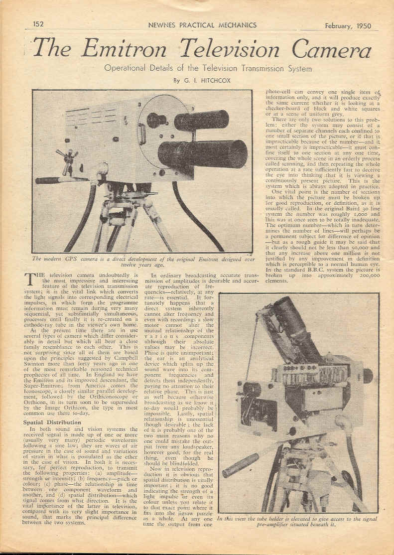
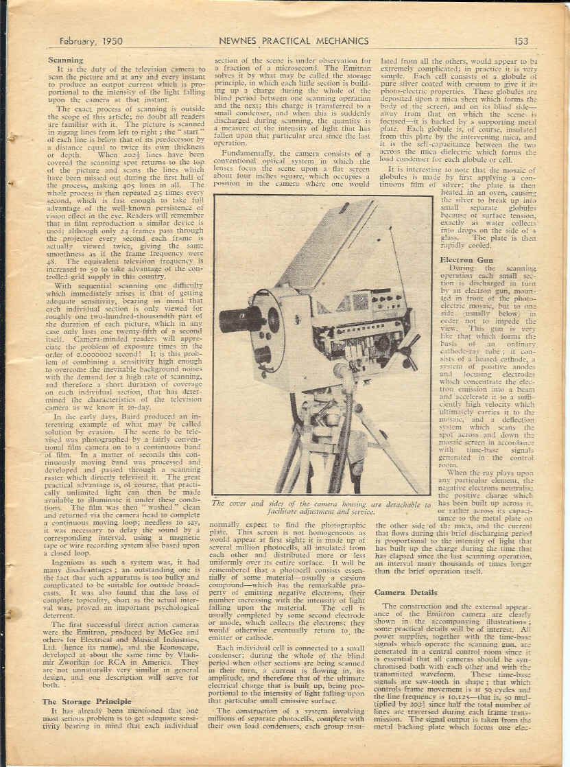
caption The modem CPS camera is a direct development of the original Emitron designed over twelve years ago. caption In this view the tube holder is elevated to give access to the signal pre-amplifier situated beneath it.
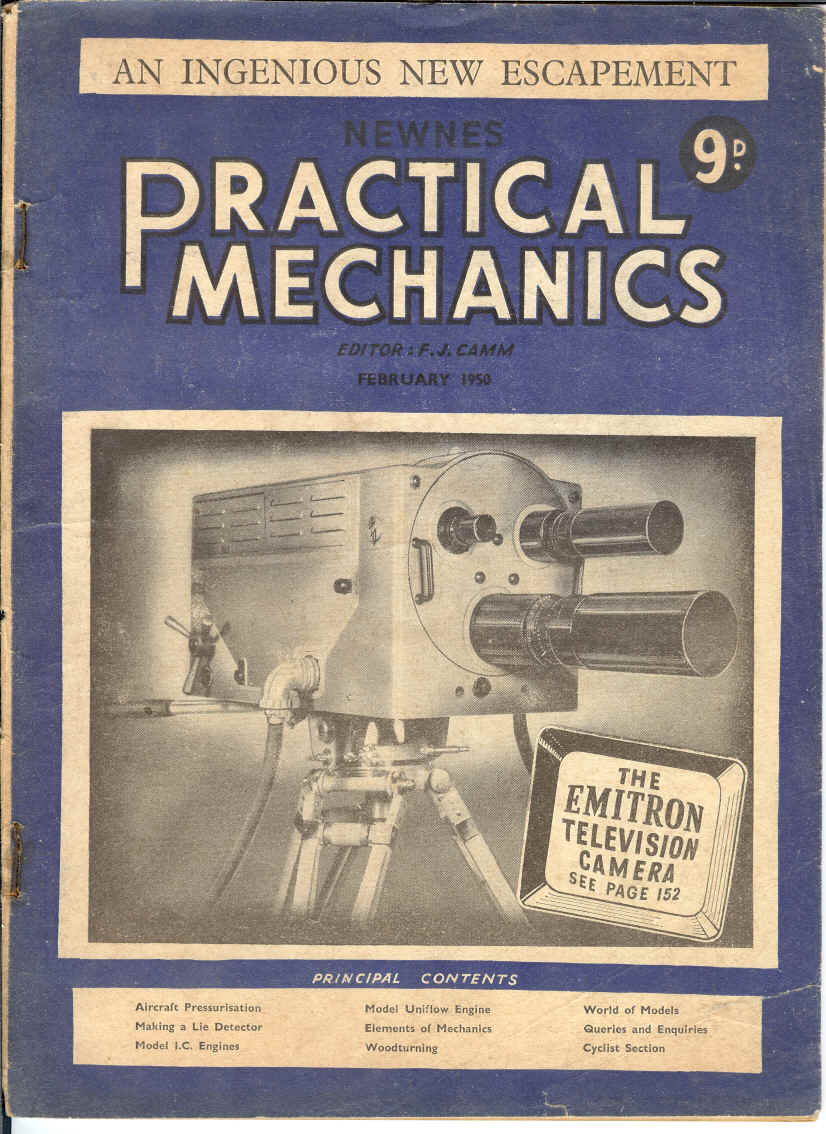
15 3 NEWNES PRACTICAL MECHANICS February, 1950Scanning It is the duty of the television camera to scan the picture and at any and every instant to produce an output current which is proportional to the intensity of the light falling upon the camera at that instant. The exact process of scanning is outside the scope of this article; no doubt all readers are familiar with it. The picture is scanned in zigzag lines from left to right; the" start" of each line is below that of its predecessor by a distance equal to twice its own thickness or depth. When 2o2 1/2 lines have been covered the scanning spot returns to the top of the picture and scans the lines which have been missed out during the first half of the process, making 405 lines in all The whole process is then repeated 25 times every second, which is fast enough to take full advantage of the well-known persistence of vision effect in the eve. Readers will remember that in film reproduction a similar device is used; although only 24 frames pass through the projector every second each frame is actually viewed twice, giving the same smoothness as if the frame frequency were 48. The equivalent television frequency is increased to 50 to take advantage of the controlled grid supply in this country. With sequential scanning one difficulty which immediately arises is that of getting adequate sensitivity, bearing in mind that each individual section is only viewed for roughly one two-hundred-thousandth part of the duration of each picture, which in any case only lasts one twenty-fifth of a second itself. Camera-minded readers will appreciate the problem of exposure times in the order of 0.0000002 second! It is this problem of combining a sensitivity high enough to overcome the inevitable background noises with the demand for a high rate of scanning, and therefore a short duration of coverage on each individual section, that has deter-· mined the characteristics of the television camera as we know it to-day.In the early days, Baird produced an interesting example of what may be called solution by evasion. The scene to be televised was photographed by a fairly conventional film camera on to a continuous band of film. In a matter of seconds this continuously moving band was processed and developed and passed through a scanning raster which directly televised it. The great practical advantage is, of course, that practically unlimited light can then be made available to illuminate it under these conditions. The film was then "washed" clean and returned via the camera head to complete a continuous moving loop; needless to say, it was necessary to delay the sound by a corresponding interval, using a magnetic tape or wire recording system also based upon a closed loop.Ingenious as such a system was, it had many disadvantages; an outstanding one is the fact that such apparatus is too bulky and complicated to be suitable for outside broadcasts. It was also found that the loss of complete topicality, short as the actual interval was, proved an important psychological deterrent. The first successful direct action cameras were the Emitron, produced by McGee and others for Electrical and Musical Industries, Ltd. (hence its name), and the lconoscope, developed at about the same time by Vladimir Zworykin for RCA in America. They are not unnaturally very similar in general design, and one description will serve for both. The Storage Principle It has already been mentioned that one most serious problem is to get adequate sensitivity bearing in mind that each individual section of the scene is under observation for a fraction of a microsecond. The Emitron solves it by what may be called the storage principle, in which each little section is building up a charge during the whole of the blind period between one scanning operation and the next; this charge is transferred to a small condenser, and when this is suddenly discharged during scanning, the quantity is a measure of the intensity of light that has fallen upon that particular area since the last operation.Fundamentally, the camera consists of a conventional optical system in which the lenses focus the scene upon a flat screen about four inches square, which occupies a position in the camera where one would normally expect to find the photographic plate. This screen is not homogeneous as would appear at first sight; it is made up of several million photocells, all insulated from each other and distributed more or less uniformly over its entire surface. It will be remembered that a photocell consists essentially of some material-usually a caesium compound-which has the remarkable property of emitting negative electrons, their number increasing with the intensity of light falling upon the material. The cell is usually completed by some second electrode or anode, which collects the electrons; they would otherwise eventually return to the emitter or cathode.Each individual cell is connected to a small condenser; during the whole of the blind period when other sections are being scanned in their turn, a current is flowing in, its amplitude, and therefore that of the ultimate electrical charge that is built· up, being proportional to the intensity of light falling upon that particular small emissive surface. The construction of a system involving millions of separate photocells, complete with their own load condensers, each group insulated from all the others, would appear to be extremely complicated; in practice it is simple. Each cell consists of a globule pure silver coated with caesium to give it it, photo-electric properties. These globules are deposited upon a mica sheet which forms the body of the screen, and on its blind side - away from that on which the scene is, focused-it is backed by a supporting metal plate. Each globule is, of course, insulated from this plate by the intervening mica, and it is the self-capacitance between the two across the mica dielectric which forms load condenser for each globule or cell.It is interesting to note that the mosaic of globules is made by first applying a continuous film of silver; the plate is then heated in an oven, causing the silver to break up into' small separate globules, because of surface tension, exactly as water collects into drops on the side of a glass. The plate is then rapidly cooled.Electron Gun During the scanning operation each s111all section is discharged in turn. by an electron gun, mounted in front of the photoelectric mosaic, but to one side (usually below) in. order not to impede the view. This gun is very like that which forms the basis of an ordinary cathode-ray tube; it consists of a heated cathode, ????? system of positive anodes and focusing electrodes, which concentrate the electron emission into a beam and accelerate it to a sufficiently high velocity which ultimately carries it to the mosaic, and a deflection system which scans the spot across and down the mosaic screen in accordance with time-base signals generated in the control room.When the ray plays Upon any particular element, the negative electrons neutralise the positive charge which' has been built up across it, or rather across its capacitance to the metal plate fin the other side of the mica, and the current that flows during this brief discharging period is proportional to the intensity of light that has built up the charge during the time that has elapsed since the last scanning operation., an interval many thousands of times longer than the brief operation itself. Camera Details The construction and the external appearance of the Emitron camera are clearly shown in the accompanying illustrations~ some practical details will be of interest. power supplies, together with the time-base signals which operate the scanning gun, are generated in a central control room since it is essential that all cameras should be svnchronised both with each other and with 'the transmitted waveform. These time-base signals are saw-tooth in shape; that which controls frame movement is at 50, cycles and the line frequency is 1O,125-that is, 50 multiplied by 202 1/2 since half the total number of lines are traversed during each frame transmission. The signal output is taken from the metal backing plate which forms one elec-caption - -The Cover and sides of the camera housing are detachable to facilitate adjustment and service.
15 4 NEWNES PRACTICAL MECHANICS February, 1950trode common to all the individual load condensers ;. it is taken direct to a· cathode follower, which acts rather like a step-down transformer, but without any large reduction in voltage. The output from this. is. amplified several hundred times by an internal valve unit, in order to raise the signal well above any normal interference level, and then fed via a second cathode follower to the cable which connects the camera to the control room and ultimately to the modulation circuits of the transmitter. All the variations to the Emitron are similar in general principle, and a brief description of one will suffice. The Super-Emitron, the instrument most widely used in this country, separates the functions of photo-electric cell and storage condenser. The light is focused on to a continuous transparent sheet which emits electrons from its reverse side in proportion to the light falling upon each particular area. These electrons arc drawn away in strictly parallel lines to a second sheet, which is a mosaic but without any photo-electric properties. The action of the primary electrons in striking this second screen disturb many other electrons-it is the possibility of a multiplicative effect due to secondary emission which forms the main advantage of the Super-Emitron-and each individual unit of the mosaic is sequentially scanned by a cathode-ray beam exactly as in the original instrument.
|