| JOHNSON
      RADIO CATALOG - SCAN courtesy of K5JWK; catalog courtesy of Johnson
       CARDWELL
      VHF-UHF OSCILLATOR (This uses acorn tubes) From the E. Sharpe 
      collection at SMECC 
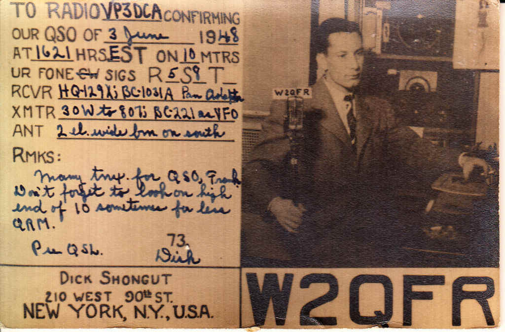
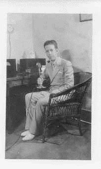
     | 


            | 


             | 
           
          
            |  
                 
              Brophy Radio Club QSL Cards 
                 | 
            
       
              Joseph Reinert's Amateur
              Radio License 
                
              Joseph Reinert
              at Mountain Bell  | 
           
          
            |   | 
              | 


                Joseph Reinert, better known as Joe, was born
                in Chicago, Ill. In 1948 he 
                and his family moved west to Phoenix, AZ. Shortly after moving
                to Arizona he 
                obtained a job with the telephone company and worked for nearly
                40 years 
                throughout all the changes. He started out climbing the poles
                and worked 
                into installation, mobile phone shop, and the microwave towers
                for various 
                radio and television stations. He worked on many of the radio
                and television 
                loops, as he called them, for big events in Phoenix. I remember
                he worked on 
                the loop when JFK came to downtown Phoenix and my Dad brought my
                sister  
                and I to his work section so we could see a close up of Mr.
                Kennedy. It was 
                exciting to know he was around some famous people. He also
                worked on big 
                television projects such as the Phoenix Open Golf Tournament.


                In the early 1960's he became interested in being
                an Amateur Radio Operator. 
                Our kitchen was filled with radio equipment that was placed
                against the wall 
                from one end to the other. Many days and nights he would sit and
                I could 
                hear "CQ, CQ, CQ6, this is K7HYG in Phoenix, Arizona is
                anyone out there". I 
                was amazed at how many people were on the radio. He received
                numerous  
                cards from all around the United States. He designed his own
                card and was 
                 involved with the Brophy College Preparatory School Radio
                Club and designed  
                their call card also. My Mom assisted with the design and then
                proceeded to  
                do the silk screening to print the cards.


                After his passing we found some of his radio
                equipment , cards, and a 
                picture. I contacted Ed Sharpe after looking for a home for his
                memories to 
                be displayed. Ed was very gracious and told me that he was going
                to do some 
                research to see if he could find more information regarding
                Dad's 
                communication experience.  I am so looking forward to
                seeing a part of my 
                Dad's life being reflected in the SMECC museum.


                 | 
           
          
            | what is a loop?
                 
              by Bert Wiener 
                
              Bert Wiener and Associates 
              Well, a loop is a Telco term that generally
              refers to a circuit - mainly between a customer and a C.O., or
              between the two ends, at least that's the way I've always heard it
              used.  I dealt with a lot of "Program Loops", or
              circuits over the years.  For example, when doing the Los
              Angeles Philharmonic Orchestra broadcasts, we'd order a 15 kHz
              loop, or circuit, sending from the Music Center to our studio's on
              Wilshire Boulevard.  Prior to the advent of ISDN, program
              circuits were in common use between a remote broadcast location
              and the studio.  Still, today, it's not uncommon to have a
              loop, or program circuit carrying a station's audio from its
              studio to its transmitter.  Program loop/s is a way to get
              good quality audio from one point to another short of running your
              own wire out the door and down the street. 
               
              Prior to satellite delivery, network feeds, such as the Mutual
              Network, CBS, ABC and all the others all pretty much depended on
              Telco program circuits. 
               
              Common program circuit bandwidths are 8 kHz (AP3) and 15 kHz
              (AP4).  I've always gone with 15 kHz circuits because the
              installation costs were about the same and the monthly fee was
              only a few dollars (like $3 or $4 dollars) different.  15 kHz
              circuits are generally cleaner and don't present roll off in the
              same part of the spectrum as other system filters or roll offs
              might.  Having all the system filters rolling off in the same
              place can cause ringing in the audio, the same way it does in
              video.  
               
              In video the ringing can show up as anticipatory, or pre or even
              post ghosting - quite noticeable around collars and other sharp
              transitions from black to white.  In audio it can appear as
              distortion in the area of similar roll off.  I prefer having
              all bandwidth/s as wide as possible ahead of the last narrower
              filter. 
               
              Then there are "Stereo Pairs", which refer to two
              program circuits used for stereo broadcasts.  These had to be
              the same length, run over the same path, and had to equalize out
              so that the maximum phase shift between the "pairs" at
              any frequency between 50 and 15,000 CPS (Hz) was no greater than 3
              degrees measured end to end. 
               
               
                 | 
              | 


     | 
   
  
    | 
      
         
     | 
   
  
    |   | 
   
  
    | 
       
      Photographs and Cards
      of the
      late 
       
       
      Capt.
      Lyman M. Edwards USNR Ret.
      Amateur
      Radio Operator
        
      W5FJ 
      Click above to go visit
      Capt. Edwards...
          | 


      At The Museum... 
        
        
      5-T Sky Buddy at the museum. 
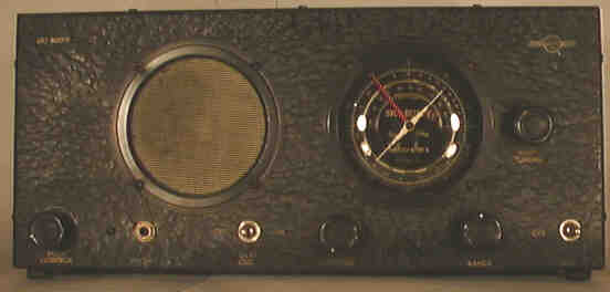
      1936, 6 tubes, 3 bands, orig. $29.95 
         
      KWS-1
 We
      have one! we
      need:  A
      set of Finals Set
      of HV cables Antenna
      Relay 75A4
      Receiver  to match  with it  


  | 
   
  
    | 
        | 


      The history of the Rubber Ducky Antenna. 
       
      I've read a lot about "Rubber Ducky" Antennas on the Web and 
      it seems that nobody knows where they came from! It seems 
      that many people think that they are just some natural outcome 
      of a typical engineering design. In fact, if a Rubber Ducky 
      Antenna did not already exist, and you put a bunch of Engineers, 
      Mathematicians, and Physicists in a design conference and 
      asked them to design one, they would properly claim that 
      it couldn't possibly work. 
       
      When I was at the Lyman School in Westborough Massachusetts, 
      a reform school for juvenile delinquents, I operated a Ham 
      Radio Station on the 6-meter phone band. My call sign was 
      K1KLR. Because space was a premium, I was unable to have an 
      outside antenna.  Therefore, I invented what became known as 
      the "Rubber Ducky Antenna". It was first called a cantenna 
      long before Heathkit borrowed the name for a dummy-load. 
      It was published in QST Magazine sometime around 1958 by 
      my mentor, Mr. Guido Sandini, who was the cottage master 
      at Westview Cottage at Lyman. Mr. Sandini was a well-known 
      "ham" who taught a "ham-radio" class at the Lyman
      School. 
       
      This is the story about that invention. 
       
      I was kind of a privileged character at Lyman, having already 
      "done my time" and awaiting out-placement. I became part of 
      a successful program where such persons were allowed to attend 
      "outside school" in Westborough. 
       
      After returning from outside school each afternoon, I was 
      supposed to use a small room at the front of Lyman Hall 
      for my homework studies. After I would barely complete my 
      homework, I would set up my Ham Radio station and attempt to 
      communicate with others in the Westborough area.  I didn't 
      have a place to install an antenna so I would connect the 
      shield of a co-axial cable to the screen of a screen-door, 
      poke the center conductor through a hole in the screen, then 
      attach a 1/4 wave-length wire to that.  This would dangle 
      outside and sometimes work as an antenna. 
       
      Some hams would refer to this makeshift antenna as "loading 
      up a screen-door". At one time I thought I heard the words 
      "screen-door spring". This make me think. The problems with 
      the wire dangling through the screen were that it was too 
      long and it wasn't properly oriented for a good antenna. 
       
      So, my first attempt at a rubber-ducky antenna was what 
      I called the "cantenna". This consisted of a paint can 
      which I filled with rocks for support. To the top of the 
      can I soldered 4 radials of brazing rod. Their length 
      was determined by the size of the floor of the closet 
      where I would store this contraption. In the center of 
      the can-lid I installed a coaxial connector so that 
      the solder connection was oriented upward from the 
      top of the can and outside the can. I Punched a hole 
      in the side of the can so that I could insert the 
      coaxial cable from the transmitter and receiver T/R 
      relay. I soldered a section of a screen-door spring 
      to the center conductor of the coaxial connector. 
       
      I found that the spring needed to be only about 10 
      inches high after I had stretched it so that none 
      of the turns touched each other. This was tuned, with 
      the transmitter at low power, by adjusting the length 
      so that a neon bulb would illuminate when brought 
      near the top of the spring and an inductive loop 
      coupled to a light-bulb would light the bulb when 
      brought near the base of the spring. 
       
      After scratching my eye while taking my portable 
      antenna down, Mr. Sandini suggested that the spring 
      be put inside a piece of windshield-wiper hose. Since 
      we didn't have "shrink-tubing" in those days, this 
      was difficult to do until I threaded a wire through 
      the spring and used it to pull the spring through 
      the tubing from the bottom of the spring so it 
      wouldn't distort and stretch out the antenna. 
       
      Mr. Sandini made some further experiments with my 
      antenna, in fact making one that required no ground 
      radials at all. It was just a spring in a rubber hose 
      with a banana plug on one end. This would plug into 
      the top-of-the-box antenna connector on the portable 
      transceivers used by the Civil Defense, the Gonset 
      Communicator III. He made several for both the six 
      and two meter amateur radio bands. 
       
      After using this antenna successfully at a "Ham Fest" 
      in Swamscot, Massachusetts, Mr. Sandini published an 
      article about it in the QST magazine. 
       
      Now, neither Mr. Sandini nor myself knew why the spring 
      worked as an antenna. My first thought for the design was 
      that I needed a spring that, when stretched out, would 
      be 1/4 wave-length long to emulate a 1/4 wave-length 
      whip. I carefully calculated the stretched-out length 
      of a spring from its circumference and wire diameter. 
      Imagine my surprise when I found out that the thing 
      would resonate, produce better than a 2:1 VSRW, and 
      actually function as an antenna, when about 1/6 
      the calculated length! Then it was thought that 
      it was the resonance alone that made it antenna-like. 
      However, this wasn't true because good coils don't 
      radiate very much energy (they are low-loss). Then 
      it was thought that the thing just acted like a base- 
      loaded whip. This turned out to be untrue as well. 
       
      Basically, the Rubber Ducky can't work as well as 
      it does. A well-constructed Rubber Ducky has a base 
      impedance near 50 ohms. This is dependent upon the 
      ratio of the diameter to length. It also has about 
      10% bandwidth.  This is dependent upon the spacing 
      of the turns, the closer the spacing, the lower the 
      bandwidth. It also has an aperture that is over twice 
      its physical size. This is the real anomaly. No 
      other antenna has an aperture greater than its size. 
       
      After I left Lyman School, I started a career that 
      has spanned over 4 decades of successful Engineering 
      Design.  I have moved from Radio Transmitter design 
      through medical Ultrasound design to Software Design 
      for CAT Scanners and Airport Baggage Scanners. Every 
      time I see somebody with a Cell-Phone, I remember those 
      beginnings. Now, if I had only Patented the damn thing! 
       
      I read about the origin of the name "Rubber Ducky". 
      It was originally called a cantenna and then a vertical 
      helical, neither of which really defined the antenna. 
      I think it was Caroline Kennedy who gave it its name 
      when pointing to one on the top of a secret service 
      security guards transceiver. 
       
      Cheers, 
       
      Richard B. Johnson 
      Project Engineer 
      Analogic Corporation 
     | 
   
  
    | 


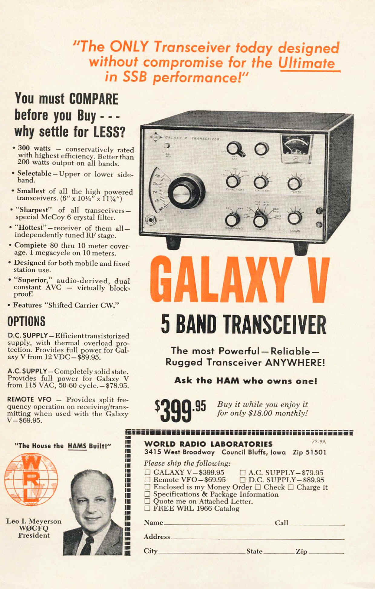
      We have a Galaxy V need a power supply though wither
      12 v  or 115 volts.  
       email info@smecc.org  with
      'Galaxy Power Supply" as subject! 
     | 
   
  
    | 
      Below are a few other things  we have in the
      collection! We are looking  for manuals  and accessories for
      most of them!
     | 


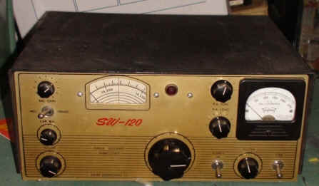
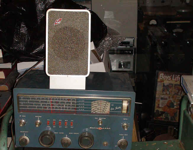
      Swan
      SW120                                                                      
      National NC-190 receiver with matching speaker
      | 


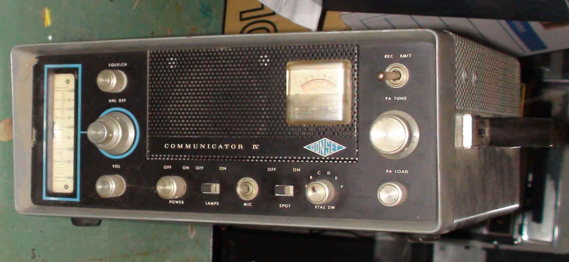
      Gonset Communicator IV  Yes defetly need manuals  for this
      one! 
      | 


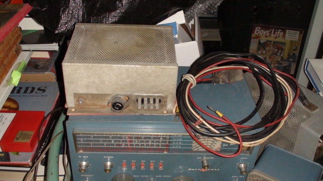
      Power supply  for???!?!  the Swan maybe??? Help.....
      | 
   
  
    | 
       
     | 


  |