|
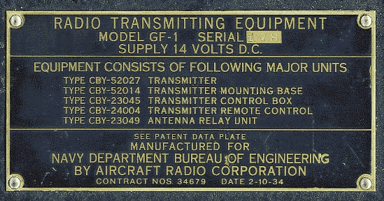
The Navy GF-1 and the Army BC-230 of radio set SCR-183
are very similar- much closer then the later GF transmitters.
It uses three type 10 tubes (CRP-38110),
two as modulators and one as power amplifier.
A 45 Special (CRP-38142, VT-52) serves as the oscillator.
The original GF, built in 1932, delivered 1.5 watts out.
The GF-1 produced 3 watts. The big design change
seems to have come with the GF-2; it and subsequent
GF transmitters gave 15 watts output.

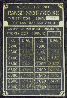
The GF and GF-1 were speced for 6600-7400 KCs only,
but did include a plug-in coil. The coil design
differs from later models in physical construction;
the antenna loading coil tap uses a swing-arm device
with lots of joints for developing intermittent connections.
The coil contacts are also arraigned differently
from those of later production coil sets.
The matching RU-3 receiver also had
a single plug-in coil for 5400-8100 KCs.
After delivery of the GF-1/RU-3 in 1934,
Aircraft Radio Corp. offered an improved design
(now with multiple coils) to the
civilian market as aircraft radio set model 457C.
The military bought this updated design "off the shelf"
and designated it "GF-2/RU-3A"
(1934 seems to have been a busy year for Aircraft Radio).
Subsequent GF/RU sets were based on this design.
While the GF/RU was a very successful Navy set with a
long service life, I do not know how well it did in
commercial service.
The only other single-frequency-range transmitter set
in this series was the GF-6/RU-8, produced for the
Naval Reserve in 1938.
The GF-6 transmitter covered 2000-4525 KC.
The RU-8 receiver did have multiple coils, but only for
the LF Radio Range band, broadcast band and 2000-5600 KC.
The GF-7/RU-9 (1938) and GF-10/RU-15 (1939)
were also produced for the Naval Reserve,
but included multiple TX coil sets.
The popular GF-11/RU-16 set produced by Western Electric
in 1941 was, in fact, not acquired as an aircraft set,
even though the nomenclature plate lists it as such.
Ships 242A specs it for Marine Corps ship installations,
and Hue has documentation on its installation in a
mechanized artillery vehicle. Photographic evidence shows
it in an ambulance and in other types of vehicles.
The last GF/RU set, GF-12/RU-17 by Western Electric,
was procured in 1941.
It is listed with two transmitter coil sets,
3000-4525 KC and 6000-9050 KC.
The RU-17 receiver coil sets do cover from the LF band
to 9050 KC, but have a coverage gap
between 4525 KC and and 5200 KC.
I haven't found a reason for this limited range.
The last two RU designs, 12-volt RU-18 and
24-volt RU-19, were used in general aircraft service
and not specifically assigned to a GF model transmitter.
These were produced by Western Electric in 1941.
Perhaps they were acquired as "upgraded" replacements
for earlier RU-series receivers, much as the third
generation of ATA transmitters was produced
as replacements/spares.
After 1941, the new-fangled GT/RBD
(later renamed ATA/ARA) eclipsed the GF/RU,
although the "roogy-foo" remained in service
with front-line units well into WW-II.
The ATA/ARA itself was to be eclipsed by AN/ARC-5.
Even so, all three sets saw long and distinguished service.
I wonder if there was intentional collaboration between
the Navy and A.R.C. to produce the refined GF/RU set of 1934.
Producing plug-in coils for a single-range set
makes sense only if you're prototyping for a later,
multi-range set. The only other single-range set
in this series was the GF-6/RU-8, produced for the
Naval Reserve in 1938. The GF-6 transmitter covered 2000-4525 KC.
The RU-8 receiver did have multiple coils, but only for
the LF Radio Range band, broadcast band and 2000-5600 KC.
I have a 1934 production A.R.C. Army BC-230 transmitter
that is the "kissing cousin" of the GF-1. Perhaps A.R.C.
collaborated with both services, the Army being satisfied
with the earlier, simpler design and the Navy buying the
later refinements.
If anyone can add to this essay,
many of us would be glad to read it.
73 DE Dave Stinson AB5S

|