Logic Trainers & Simple Computers
Home ] Up ]


IBM Digital Logic Trainer. 

 Comes in a grey wooden box with many of these pluggable modules as you see inserted and next to the trainer. Date? 50s-60s? We need to learn more about this unique unit! Please email us at  info@smecc.org if you can tell us any history on this! There has to be some IBM employees that know the history behind these trainers or maybe even have the pin out for the power supply!  
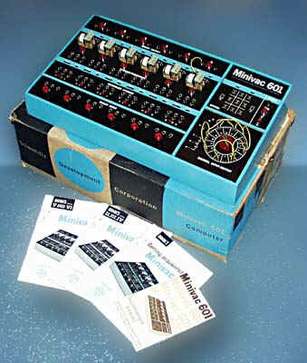
Many thanks Ed Sharpe archivist for SMECC

Scientific Development Corporation Ships the
 MINIVAC 601
 Tabletop Training Digital Computer for Around $85


MINIVAC 601

wpe1.jpg (22970 bytes)
Click on photo for larger view!


wpeA.gif (62999 bytes)

Click on photo for larger view!

wpe10.gif (131462 bytes)

Click on photo for larger view!


DIGITAL -  DEC COMPUTER LAB   1969

How many of us  cut our teeth on these?  We are interested in stories and reminiscences to post here!

wpe27.gif (410438 bytes)   Table of Contents  wpe16.gif (417884 bytes)


  • PREFACE
  • INTRODUCTION
  • OPERATING INSTRUCTIONS
  • CHAPTER 1 The Binary Concept
    • Experiment 1.1: 2-Input NAND Gate
    • Experiment 1.2: 3-Input NAND Gate
    • Experiment 1.3: 4-Input NAND Gate
    • Experiment 1.4: Inverter
    • Experiment 1.5: Substituting Gates
    • Experiment 1.6: Decimal to Binary Encoder
    • Experiment 1.7: Binary to Decimal Decoder
  • CHAPTER 2 Basic Logic Gates
    • Experiment 2.1: AND/NOR Gate
    • Experiment 2.2: NOR Gate Application of AND/NOR Gate
    • Experiment 2.3: AND/NOR Comparator
    • Experiment 2.4: AND/NOR Gate Used for Exclusive OR
    • Experiment 2.5: Non-Inverting Gate
    • Experiment 2.6: Equality Detector
    • Experiment 2.7: Parity Bit Generator
  • CHAPTER 3 Flip-Flops
    • Experiment 3.1: R-S Flip-Flop
    • Experiment 3.2: Clocked R-S Flip-Flop
    • Experiment 3.3: D Type Flip-Flop
    • Experiment 3.4: J-K Flip-Flop
    • Experiment 3.5: 4-Bit Shift Register
  • CHAPTER 4 Boolean Algebra to Gating Networks
    • Experiment 4.1: Gating Circuit Simplification
    • Experiment 4.2: Equality and Relative Magnitude Detector
  • CHAPTER 5 Binary Counters
    • Experiment 5.1: Asynchronous Binary Up Counter
    • Experiment 5.2: Modified Asynchronous Binary Counter
    • Experiment 5.3: Synchronous Binary Up Counter
    • Experiment 5.4: Synchronous Binary Up/Down Counter
    • Experiment 5.5: Synchronous Modulo 6 Binary Up Counter
    • Experiment 5.6: Asynchronous Self-Stopping Modulo 13 Binary Counter
    • Experiment 5.7: Variable Modulus Asynchronous Binary Up Counter
  • CHAPTER 6 Serial Addition
    • Experiment 6.1: Serial Adder
    • Experiment 6.2: Subtraction Using the Serial Adder
    • Experiment 6.3: Multiplication Using the Serial Adder
  • CHAPTER 7 Parallel Addition
    • Experiment 7.1: Parallel Adder
    • Experiment 7.2: Two's Complement Subtraction
    • Experiment 7.3: One's Complement Subtraction
    • Experiment 7.4: One Step Parallel Addition
  • CHAPTER 8 Binary Coded Decimal Operations
    • Experiment 8.1: The 8421 Counter
    • Experiment 8.2: The Excess 3 Counter
    • Experiment 8.3: The 2421 Counter
    • Experiment 8.4: The 5421 Counter
    • Experiment 8.5: Serial BCD Addition
  • CHAPTER 9 Code Conversion and Decoding
    • Experiment 9.1: The 2421 to 8421 Converter
    • Experiment 9.2: The 5421 to 8421 Converter
    • Experiment 9.3: Gray to Binary Converter
  • CHAPTER 10 System Considerations
    • Experiment 10.1: Parallel Adder Control
    • Experiment 10.2: Synchronizers
    • Experiment 10.3: Maximum Frequency
  • Appendix A: Checkout Procedures
  • Appendix B: Karnaugh Mapping
  • Appendix C: TTL Circuitry
  • Appendix D: The Computer
  • Appendix E: Glossary of Terms
  • Appendix F: Decimal to Binary Conversion Table
  • Appendix G: Powers of Two
  • Appendix H: Recommended Texts
  • Appendix I: COMPUTER LAB Hardware Specifications
  • Appendix J: Warranty
  • Appendix K: Logic Element Truth Tables

APPENDIX I

COMPUTER LAB HARDWARE SPECIFICATIONS

I
GENERAL SPECIFICATIONS
1.
Size -- 16 1/2" x 12 1/2" x 3 1/4" (cases are stackable).
2.
Finish -- Simulated teak.
3.
Power Requirements -- H500: 50 or 60 cps, 105 to 120 VAC; H500A: 50 or 60 cps, 210 to 240 VAC.
4.
Power Switch -- On Variable Clock Control.
II
ELECTRONIC LOGIC SPECIFICATIONS
1.
Functions Available:
8 J-K Flip-Flops (Master-Slave type)
8 2-Input NAND Gates
6 3-Input NAND Gates
4 4-Input NAND Gates
4 AND/NOR Gates
2.
Type of Circuits:
Transistor-Transistor Logic Integrated Circuits
3.
Logic Levels:
HI -- +3 volts nominal (+2.4 to +3.6 volts)
LO -- Ground nominal (0.0 to +0.4 volts)
Internal Supply Voltage: +5 volts (not available on patch panel)
4.
Input Loading:
Unit Load: 1.6 ma at GND. +40 µa at +3 volts.
Gate inputs and Flip-Flop J & K inputs present one load each.
Flip-Flop Clock and Reset inputs present two loads each.
Lamp Indicator inputs present five loads each.
5.
Output Drive:
The Fan-Out of an output indicates the number of unit loads that output can drive:
Logic outputs on the patch panel have a fan-out of 10.
Rocker Switches, Pulsers, teh Clock, and HI terminals have a fan-out of 30.
III
CONTROL AND INDICATOR SPECIFICATIONS
1.
Functions Available:
8 Rocker Switch logic level generators
3 Pulser Switches
8 Lamp Indicators
1 Variable Frequency Clock
2.
Rocker Switches:
Give HI output when upper side of switch is depressed.
Give LO output when lower side of switch is depressed.
Fan out: 30.
3.
Pulser Switches:
Normally provide a LO output.
HI output when depressed, reamin HI until released.
Fan-out: 30. Build-in switch filters.
4.
Lamp Indicators:
Normally OFF when no input.
ON when corresponding input HI.
OFF when corresponding input LO.
Load: 5 unit loads.
5.
Clock:
Repetition rate: less than 1 pulse per second to more than 10 x 106 pulses per second.
Pulse width: 50 nanoseconds nominal.
Fan-out: 30.


Everyday we rescue items you see on these pages!
What do you have hiding in a closet or garage?
What could you add to the museum displays or the library?

PLEASE CONTACT US!

===================

DONATE! Click the Button Below!


Thank you very much!

===================

Material © SMECC 2007 or by other owners 

Contact Information for
Southwest Museum of Engineering,
Communications and Computation 
&
www.smecc.org

Talk to us!
Let us know what needs preserving!


Telephone 
623-435-1522 

Postal address 
smecc.org - Admin. 
Coury House / SMECC 
5802 W. Palmaire Ave 
Glendale, AZ 85301 

Electronic mail 
General Information: info@smecc.org