| My Work With Vacuum Tubes At Bell Laboratories By John R. Pierce (c) (Reprinted from SMEC (now SMECC) "Vintage Electrics" Volume #3 issue #1 - 1991) |
|
|
|
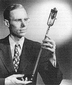
John Pierce Holding An Early Traveling Wave Tube. |
| The Early Days The date of my starting work at Bell Laboratories was to be September 1936. My parents, through a sort of general good will, and perhaps in celebration of my receiving my doctorate and getting a job, sent me on a trip through Europe during the summer. This was a slow journey by today's standards, by train and small steamer, bicycling in England and traveling by rail in France, Italy and Germany. On my return, I went back to California to see my mother and father and to collect my few belongings, and then on to New York, where I was to work at 463 West Street, in Manhattan. For two years, until I was married in 1938, I shared apartments within walking distance of work with Chuck Elmendorf (Charles Halsey Elmendorf III). Chuck had received an M.S. degree from Caltech; like me he had come to work at Bell Labs. Working at Bell Laboratories was a novel and bewildering experience. My first boss, Dick Mendenhall, had been a favorite student of Millikan's at Caltech. He was at that time a very handsome man, though his feet had been severely damaged in a high-voltage accident. I saw something angelic, and perhaps a little aloof in his features, but he treated me warmly and invited me to his home in Summit, New Jersey. I had a high regard for Mendenhall, but he gave me little guidance. Neither did Mervin Kelly, not yet president of -Bell Laboratories but somewhere way up the line. I met him at the Laboratories shortly after I got there. Someone I didn't remember having seen before stopped me in the hall and asked what I was doing. I was suspicious and asked who he was. "Mervin Kelly," he replied. Mendenhall's direct boss was Ray Wilson, a jolly and agreeable man who, like Kelly and all above Mendenhall, had an office high in the main Bell Laboratories building at 463 West Street. All who worked on vacuum tubes of Mendenhall's rank and below were in the "Biscuit Building"(a structure built for and once used by the National Biscuit Company), just north of the main building. The Biscuit Building had two floors and a basement. On the upper floor, experimental vacuum tubes were built by an organization directed by Vick Ronci. He had a few engineers and innumerable craftsmen. There were offices and office laboratories, separated by glass partitions, on the south and west sides of the ground floor. In the center was a large space for laboratory work. I did my first work in this central space. What did I do? My account must be based partly on my memory of remote days, and partly on the titles of internal technical memoranda, called Memoranda for File, that I wrote frequently during most of my years at Bell Labs. I received little guidance except that I was to do research on vacuum tubes. I was told of some work by Philo Farnsworth, and of a high-frequency oscillator with no hot cathode that he had made. Farnsworth was an ingenious inventor who never prospered largely. His image dissector was an ingenious, almost distortionless television pickup tube that was used for some years for scanning movie film for television broadcast. Unlike Zworykin's Iconoscope, the image dissector didn't involve storage, and it was not sensitive enough to pick up live scenes with reasonable lighting. I finally visited Farnsworth's laboratory, no doubt with others, and I took back with me one of his oscillator tubes, which I tested and came to understand. It wasn't of any practical value. More important, I saw the electron multipliers that he incorporated in his image dissector and in other devices. These seemed to me to be crude and unduly complex in construction. So did the magnetically focused electron multipliers the Myron Glass, a colleague at Bell Laboratories, had built. It was Myron Glass who said, truly, "Nature abhors a vacuum tube," a remark later attributed to me. Wasn't there a way to design a simple, effective electrostatically focused multiplier? To do this, one needed a way to find where electrons would go in a system of odd-shaped electrodes. The conventional approach would have been to find the electric field, analytically (impractical) or experimentally in an electrolytic tank, and then to compute the electron trajectories (impractical in those pre-computer days). At this time I came to know Bill Shockley, a new employee who was making the rounds of various parts of the research department. His effect on vacuum-tube research was electrifying, in his work with others as well as with me. It was because of him that a practical means for designing electron multipliers was worked out. At this point I really don't remember whose idea it was; it may well have been Shockley's. Certainly, he had a lot to do with the construction. Electric potential in a two-dimensional system of electrodes is analogous to physical height. An electode at a given potential is analogous to a level surface. Moreover, the height of a stretched sheet of thin rubber supported by "electrodes" of various heights is closely but not exactly analogous to the electric potential between actual electrodes of the same shapes. In this rubber sheet analogy, the electric potential (height) and the electric field (slope) appear before ones very eyes. And, even better, by rolling ball bearings down the stretched rubber one can find very nearly, and certainly nearly enough, where electrons will go in the analogous electric fields. With this tool, it was easy to find a common shape for succeeding opposed and staggered electrodes at progressively higher potentials that would focus the secondary electrons from each electrode effectively on that of the next higher potential. The electrode shapes that I worked out proved very effective in the photomultipliers that the tube shop on the second floor constructed for me. In 1941 I finally published a paper on this electrostatically focused photomultiplier with a colleague, R. C. Winans, who had made an improved structure. Electron multipliers of similar design are used today. A patent was applied for. Similar work had been done about the same time at RCA. I don't know who got the patent. In the course of my work on electron multipliers, I became concerned with the noise in the output of these devices. Shockley worked out a theory. I simplified it. We published a paper on this in the March, 1938 issue of the Proceedings of the IRE. As a part of an internal review of this work on noise, Thornton Fry, head of the mathematics department at Bell Labs, and a very eminent and useful industrial mathematician, objected to the description of the noise as a signal with an infinitely broad, flat power spectrum. He felt that this was mathematically unsound. He had published work on shot noise in which the properties of the output circuit, with limited bandwidth, were an integral part of the expression for noise. This avoided the to him mathematically unsound idea of a fluctuation of infinite bandwidth. But, Shockley's approach, really not new, gave the same answer as Fry's and was less cumbersome and specialized. Fry appeared not to understand this. This reinforced in me a distrust of authority, even sound authority. I soon found that there wasn't any use in the Bell System for a better photomultiplier. Broad band coaxial cable systems capable of transmitting hundreds of telephone conversations or a television signal were just coming into being. There was a great need for amplifier tubes with high transconductance (the ratio of the current change at the plate to the voltage change at the grid) and low input and output capacitance. I thought that electron multipliers might be useful in producing such tubes. Others had the same idea, and a few experimental tubes were produced and marketed, but were not really successful. The electron multiplier could be used to increase the transconductance by producing several electrons for one, but this also increased the output current. Ahead of the electron multiplier one needed a means for controlling electron flow that would give a large transconductance per unit current. In the conventional cathode-grid arrangement invented by Lee De Forest, there was an inescapable limit to this ratio, a limit due to the thermal velocities of electrons leaving the cathode. What about deflecting a beam of electrons past a sharp edge? Could the limitation be overcome in this way? The answer proved to be yes, but I didn't know enough physics to give a sound general treatment of the problem. Shockley came to the rescue, and introduced me to Liouville's theorem, which says that the density of particles in phase space (the coordinates of phase space are position and momentum) is constant. If we regard the motion of electrons as governed by the electric (and magnetic) fields in which they move, and disregard interactions of one electron on others, this applies to electrons in vacuum tubes, and the coordinates are the three position coordinates and the three velocity coordinates. The derivation of Liouville's theorem that Shockley gave me used Hamilton's equations, about which I knew nothing, but I found that the theorem could be derived easily from Newton's laws of motion, and I suppose that's how Liouville derived it. On October 13, 1937 Shockley and I issued a joint memorandum, Maximum Attainable Current Densities and Deflection Type Tubes, in which we described this work, which led to the same results that David Langmuir had derived by somewhat different means and published about that time. I published a paper, Limiting Current Densities in Electron Beams in the Journal of Applied Physics in October, 1939. Once I understood that it should be possible to attain a higher ratio of transconductance to current in a deflection tube than in a conventional tube using a cathode and grid, I set about to make a good deflection tube. The idea was new to me, but I found later that it was an old idea. The tubes I made turned out to have a substantial transconductance without any electron multiplication, and low input and output capacitance as well. Maybe a deflection tube without any following electron multiplier would be useful. In order to make a better tube, I needed a well-focused electron beam of several milliamperes at a voltage of a couple of hundred volts. Conventional electron gun designs were unsuitable. The usual approach was to settle on the shapes of an electron-emitting cathode and plausible accelerating electrodes, and to try to calculate where the electrons would go-or, simply to build the structure and see what happened. But, how was one to find a good cathode and electrode structure? And, how was one to calculate the electron paths near the cathode, where the fields were in part determined by the space charge of the electrons themselves? Several sorts of electron flow were known; the appropriate calculations had been made. These were electron flow between an infinite parallel plane cathode and an infinite parallel plane anode, flow between a cylindrical cathode and a central cylindrical anode, and flow between a spherical cathode and a central spherical anode. None of these was physically feasible. It occurred to me that one might realize a part of such flow, a cylindrical beam between parallel anode and cathode, a wedge-shaped flow between a segment of a cylinder and another segment of a cylinder, or conical flow between two spherical caps. I found out that this could be done by using electrodes outside of the beam shaped so that they would fool the electrons in the beam into thinking that they were part of a larger planar, or cylindrical, or spherical flow. At the anode one could simply cut a hole to let the electrons pass. This would act as an electron lens of calculable properties. I published this work in a paper, Rectilinear Flow in Electron Beams in the Journal of Applied Physics in August of 1940. Before that, I had given a paper at either an IRE or an American Physical Society meeting. The structure (or structures) I had devised became known as the Pierce gun, widely used in all sorts of electron devices. One other problem remained in deflection tubes-the limitation in current density through beam spreading due to the charge in the electron beam. On April 22, 1938 Ray W. Sears and I issued a Memorandum on this subject. An elaboration of this work went into my book Theory and Design of Electron Beams, published by Van Nostrand in 1949. I don't know whether or not I published a paper on the subject. What about deflection tubes? After a year or so of work, the ratio of transconductance to capacitance was almost as good as that of the pentodes that were made when I had started, but pentodes continued to improve. Further, it became apparent that the transit time of electrons in a vacuum tube had an important bad effect when such tubes were used in negative feedback amplifiers, which were essential in coaxial cable systems. Deflection tubes, with their long transit time, and electron multipliers, which also had a long transit time, would be useless in the amplifiers needed. That was the end of my work on multipliers and the deflection tubes to which that work led. What was left of all this work? I had learned to understand noise, in photomultipliers and other devices. I had become acquainted with Liouville's theorem and its implications for electron devices. I had invented an electron gun that was to have great importance in many devices, including the traveling-wave tubes used in communication satellites. I had made subsequently useful calculations on the effect of-space charge in electron beams. And, I had come to have a high regard for Bill Shockley, who was good and helpful to me, and was often good fun as well. Memories Of Microwave Tubes Sometime after I came to Bell Labs J. 0. McNally became my direct boss. Canadian by birth, a large man, good humored, he took a more direct technical interest in what I did than Mendenhall had. Still, what I actually did seemed entirely up to me. My work on electron multipliers resulted in an excellent device for which there was no use in the Bell System. My efforts to make high transconductance tubes through electron multiplication and deflection tubes came to nothing but a liberal education and knowledge that would be useful later. I had also tried some other unsuccessful approaches. Somehow, I became involved with microwaves, which seemed to be the coming thing for broad-band long-distance communication. Later this work was to be turned to wartime radar, but when I first visited Harald Friis's laboratory at Holmdel, New Jersey, the emphasis was entirely on communication. What was lacking was satisfactory microwave tubes. When I began my work, the only microwave source I had was a triode that would barely oscillate at a wavelength of 20 cm. This tube was mounted in a waveguide (a cylindrical metal tube) about four inches in diameter. This waveguide would not transmit 20 cm waves, but it would transmit 10 cm waves, the second harmonic of the 20 cm oscillator. A little second harmonic leaked out, and this I used as a source of microwave power for my experiments. The titles of my Memoranda for File indicate to me that I started to think about microwave devices in the latter part of 1938. A memorandum titled A Magnetron Amplifier puzzles me; I don't have the slightest idea what it may have been. By then, Varian had invented the klystron, and Hansen of Stanford had made an analysis of its operation. Si (Simon) Ramo, who had received his Ph. D. from Caltech at the same time that I did, had gone to General Electric. There he and Hahn had studied the operation of klystrons, and had worked out a useful theory of waves on electron streams to explain their operation. Might not the klystron be a useful amplifier? Arthur Samuel, who had been at Bell Laboratories for some years before I arrived, thought so. He built some ingenious klystron amplifier tubes that were ultimately used in the first experimental inter-city microwave system, that linking Boston and New York. Like other klystrons, these used a long, narrow electron beam, and operated at a voltage of over a thousand volts. I regarded 300 volts as more reasonable, and set out to build an amplifier which would work at that voltage. Such a klystron amplifier would have to incorporate closely-spaced pairs of grids in its input and output resonators. Designing such a tube called for an analysis different from that used by Hansen and by Ramo and Hahn. Happily, Llewellyn and Peterson of Bell Labs (I came to know both well) had published equations for ac fluctuations on an electron stream flowing between parallel planes. These equations related the velocity and current fluctuations at the second plane to the velocity and current fluctuations at the first plane. They included the effect of a voltage fluctuation between the two planes; this I did not need. Benham, a British worker, had published similar equations, but I found that he had somehow omitted a term that gave the effect of bunching due to velocity modulation-the very heart of klystron operation. Armed with these equations, I set out to design a low voltage klystron amplifier. I realized that the bunching and hence the gain would be most effective if the beam was slowed down in the drift space between the input and output cavities, so I put a low-voltage grid between these. The result was an amplifier with a gain of around 10 db. My boss, J. 0. McNally, was impressed. By that time Bell Laboratories had become involved in wartime, or pre-wartime, radar work, and he wanted to try the tube as an amplifier at the front end of a radar receive. I calculated how noisy it should be, and felt sure that it would be much too noisy. Nonetheless, I made a portable power supply and packaged the amplifier so that it could be carried easily to a Bell Labs radar operating somewhere out in the country- not at Holmdel. The amplifier improved the performance of the radar, which was much noisier than it should have been. Nonetheless, I knew that the amplifier wouldn't help a good radar, and I managed somehow to discourage further attempts at its exploitation. This was easier because of a mistake I made in using the amplifier. Accidentally, I made the grid between the input and output cavities negative rather than positive, so that it reflected electrons back through the input cavity. The tube oscillated like mad, and one could get on unprecedented 100 milliwatts from the input cavity. Further, the frequency could be changed by tuning one cavity, and the frequency could be changed by around 20 megahertz simply by changing the negative voltage of the reflecting electrode. This proved useful in automatic tuning, to make the receiver track fluctuations in transmitter frequency. I immediately made a tube with one resonator with one pair of grids and a negative reflecting electrode or reflector. This became the 707A, which was used in all 10 cm or S Band American radars. It came to be called the McNally tube. I don't claim to have invented the reflex klystron; I stumbled on it. A tube described earlier by Ramo was pretty close. Perhaps Varian or Hansen had patented the device. The virtue of the reflex klystrons we produced at Bell Laboratories for radar use was that they were simple, low voltage devices that worked well. After the 707A, we set out to make an X Band klystron, one that would work at a wavelength of 3 cm. McNally felt that a tube with a glass envelope and an external resonator, a scaled-down version of the 10 cm tube, would be practical. We tried to make such a tube, but never produced one that was any good. I thought we would have to make a tube with an internal resonator. So did Gerry Shepherd (W. G. Shepherd), who had somehow been assigned to work with me. Tubes with internal resonators had been made at Stanford, but they were high-voltage devices of complex construction that looked like the work of a German machinist. Indeed, I found out that they were. What we needed was a low voltage tube that was simple and cheap to produce. Some years earlier there had been a passing fad for vacuum tubes with metal envelopes. The Bell Labs tube department had acquired machinery for fabricating such tubes. Metal tubes proved inferior to tubes with glass envelopes, and our machinery for making them was stored away, gathering dust. At my urging, Gerry Shepherd set out to design a really satisfactory metal klystron with an internal resonator. I felt that this was a job beyond the imaginative skills of the engineers on the second floor who fabricated tubes. Gerry learned about the capabilities of the machines for fabricating metal tubes, and he sat down at the drafting board and designed the X Band oscillator himself. Years later he told me that he had felt this work a little beneath his dignity, but he didn't object at the time. The tube, the 723A, was a tremendous success, and inexpensive to fabricate. It was used in all American X Band radars. It came to be known as the Pierce-Shepherd tube. The success of this X Band oscillator led us to build a similar metal oscillator for use at a wavelength of 7.5 cm. Here we ran into trouble. The electronic tuning didn't work right. Eventually we found that the trouble was caused by reflected electrons getting clear back to the cathode region, being reflected by the cathode, and going through the resonator a second time. We remedied this by a change in the reflector electrode that cause the returned beam to spread out. By the end of 1943 we had a satisfactory tube. I then set out to make a K Band reflex klystron, that would oscillate at a frequency of 1.25 cm. In this tube the cavity was so small that it was tuned by the expansion of a metal rod heated through bombardment by electrons. The tube worked, but was never used. I had jumped to an erroneous conclusion. I had assumed that the high current density necessary in a K Band tube would preclude the use of grids, and I designed a tube without grids that operated at 750 volts. Victor Neher, a cosmic-ray physicist then working at the MIT Radiation Laboratory, was smart enough to calculate the grid temperature. He found that in a 300-volt tube of plausible design the grids would get red hot, but radiation of heat would keep them from melting. A tube following his design, but built at Bell Laboratories, became the standard K Band tube of the War years, and the years thereafter. By altering the resonator and adding grids, I turned my 1.25 centimeter tube into a .625 centimeter oscillator which George Mueller used at Holmdel in some measurements of rain attenuation. By this time I was concerned mainly with traveling-wave tubes, and I made no more of these oscillators. When they wore out, the tube development department tried, unsuccessfully at first, to duplicate them. Eventually an excellent engineer produced an excellent tube. But that was all after the war, when tube work had moved to the new Murray Hill Laboratories. After the war, Gerry Shepherd and I published a long paper in the Bell System Technical journal, telling all we knew and all we had done concerning reflex klystrons. Gerry went away to the University of Minnesota, where, after a distinguished career in electronics, he became a vice president. I turned to other matters. It seems appropriate to mention that Vic Neher, whose K Band klystron had beat mine out, did another important piece of work that affected work at Bell Laboratories. Around July, 1943 Jack Morton, who then worked for me, and I went the MIT Radiation Laboratory to see Neher's 10 centimeter triode amplifier. The secret of success was the very fine grid and the very small cathode-to-grid spacing, about a thousandth of an inch. In Neher's tube this spacing was changed a little in tuning the internal input resonator. I was much impressed by this result, but I felt that a practical tube would have to have a fixed cathode-to-grid spacing. I felt that this could be attained by attaching the cathode to a ceramic disc with a hole in it and grinding the cathode surface flush with the ceramic surface. Then a taut tungsten grid wound on a flat tungsten washer could be spaced from the cathode by a thin metal shim. I suggested to Jack Morton, who then worked with me, that he try to do this. He succeeded magnificently, on his own, when I was no longer his boss. He set up a spotlessly clean shop for producing this tube, which became known as the Morton triode. Morton triodes were used in preference to traveling-wave tubes in the first Bell System transcontinental microwave repeater system. During the war I had profited greatly from the work of others. I was in touch with work in England as well as in America. From Britain I received regularly the classified reports of the CVD (Committee for Valve Development). The minutes of this committee described in some detail work in various laboratories, industrial as well as government. At no other time have I felt so close to the unfolding of important work. From October 27, 1944 through December 23 of that year, a colleague, Homer Hagstrum, and I visited British tube laboratories for the U. S. Navy, and for our benefit as well. Hagstrum was engaged in work on cavity magnetrons, whose large pulsed power had made microwave radar feasible. I was known chiefly for my work on reflex klystrons, but I had other interests on this trip. I had read about the traveling-wave tube, which went beyond ideas that I had been exploring. I note among the Memoranda that I wrote one dated August 7, 1941, Negative Attenuation of Space Charge Waves. Sergei Schelkunoff had calculated the attenuation of the space charge waves described by Hahn and Ramo in case the material outside of the electron beam was lossy or dissipative. He found a wave with a negative attenuation, that is, a growing wave, which he thought nonsensical. I must have summarized his work without understanding its implications. Years later, the resistive-wall amplifier was invented independently, a device that made use of this forgotten phenomenon. I missed an opportunity. I worked out the action of a circuit with a slow electromagnetic wave on electrons with the velocity of the wave, but I didn't think of any circuits that could be fabricated easily. I didn't build anything. And, in my analyses, I did not go on to investigate the effect back on the circuit of an electron beam which had been bunched by the action of a slow wave having a velocity near to that of the electrons. I was looking for some novel type of microwave vacuum tube, but I didn't find it. What I didn't find for myself, I found in a CVD report. This was the traveling-wave tube, invented by Rudolf Kompfner. When Hagstrum and I were in England in 1944, I met Kompfner himself. The traveling-wave tube was to be the focus of my activities, and of those of many others, until I abandoned work on vacuum tubes. Traveling-Wave Tubes Work on traveling-wave tubes occupied most of my time from 1945 until around 1955- a period of 13 years. Today, when vacuum tubes survive almost entirely as extremely high-power devices, and solid-state devices serve almost all low-power and moderate-power functions, the traveling-wave tube is still used in some communication satellites as a transmitter producing around 10 watts. The inventor of the traveling-wave tube was Rudi (Rudolf) Kompfner. He was born in Austria, he emigrated to England, and on December 27, 1951 he came to Bell Laboratories. He was my very dear friend. You can read his account of the invention in his book, The Invention of the Traveling-Wave Tube-that is, if you can find a copy. A continuing theme of the book is that Rudi not only speculated; he built things, and he made measurements, looking for the expected and sometimes finding the unexpected. The very high gain of the traveling-wave tube was unexpected. Rudi was taken out of detention as an enemy alien in 1941, and he was, as he said, more or less drafted into the physics department of the University of Birmingham, where Boot and Randall had invented the multicavity magnetron, the centerpiece of microwave radar. He was, however, not assigned to work on magnetrons; rather, he was told to develop a klystron amplifier with a noise figure that would be better than that of existing radar receivers. In early 1944 Kompfner was transferred to a microwave tube research group at Oxford, and that is where I met him on either November 15 or 16, 1944. 1 had already heard of his work through CVD reports. Kompfner had created a device in which a slow electromagnetic wave acted on a stream of electrons, bunching them, and the bunched electron stream in turn increased the amplitude of the electromagnetic wave as it traveled along. Kompfner analyzed the process as a series of steps the effect of the wave on the electrons, the effect of the electrons on the wave, and so on, back and forth. His young colleague, Joseph Hatton, summed the resulting series and showed that there would be an exponential growth of power along the helix. The various analyses that I had done of electron flow made it easy for me to formulate the behavior of the traveling-wave tube in terms of waves. Part of the initial excitation of the signal went into one growing wave, which increased exponentially and provided the output power. The first reference to such an analysis I can find is a Memorandum titled Electronic Analysis of Traveling Wave Amplifier-II, dated November 30, 1945. I wonder, what happened to part 1? Other analyses followed in 1946 and 1947. In 1946 a popular piece about traveling-wave tubes appeared in the Bell Laboratories Record, and in February 1947 I published a theoretical paper in the Proceedings of the IRE. During this period I had made traveling-wave tubes, and they worked, giving gains of tens of db. This was at a time when Kompfner had become somewhat disillusioned with his invention, and worked for a while along other lines. He used to say that he had invented the traveling-wave tube, but that I had discovered it. Certainly, I saw the value of the traveling-wave tube the very moment I learned of it. Kompfner had seen the tube chiefly as a low-noise amplifier. I saw it chiefly as a broadband amplifier. At that time I had visions of extremely broad-band digital microwave signals, and the tube seemed the answer to my dreams. I was only partly right. Although traveling-wave tubes have been used to amplify very broad-band signals, they are chiefly used for signals with a few tens of megahertz bandwidth. Aside from the high gain and good efficiency of traveling-wave tubes, a chief advantage is that the circuits that shape and limit the bandwidth are outside of the tube itself, and can thus have an electrically and mechanically good design, and can be adjusted easily. I understood very well that a helix had negligible loss in the backward direction, and that if the tube had gain in the forward direction it was likely to oscillate. I calculated the effect of loss in the helix on the gain of the tube and found that a lot of loss would reduce the gain only a little. So, I made my tubes lossy. Further calculations showed that it would be best to put loss near the middle of the helix only, thus, in effect, dividing the tube into input and output regions, and this I did. In my early work I was much helped by Les (Lester M.) Field, who found traveling-wave tubes more interesting than the magnetrons he had been working on, and joined me in my work. After a few years he went to Stanford and established traveling-wave tube work there; he later went to Caltech, and thence to Hughes. Others joined with me in my work; Nelson Wax, Bill Hebenstreit, Art Hollenberg. By the time we moved the work from West Street to the Murray Hill Laboratories, around 1949, Sid (Sidney) Millman and I, as joint "subdepartment heads" had a considerable group working on tubes, and mostly on traveling-wave tubes of one sort or another. The group included Al Clogston, an able physicist who later, with Millman, turned to work more directly in his field, and Cal Quate and Ping King Tien, two of Les Field's students from Stanford. Rather than trying to give a completely coherent account of what I and those associated with me did in our work on microwave tubes, I shall select a few topics only. In my early work on traveling-wave tubes, I learned a lot of things not to do. Here was a wonderful device that should be cherished and improved. I wanted to excel or supplant it. I thought at first that I would combine the efficiency of the magnetron with the amplifying properties of the traveling-wave tube. Nothing came of this except wasted time, on the part of myself and others. Traveling-wave magnetron amplifiers were pursued elsewhere for many years, with indifferent success. One of the most pronounced features of electron flow in crossed electric and magnetic fields is instability, fine in oscillators but deadly in amplifiers. In late 1947 Bill Hebenstreit and I made an astonishing invention. This was the double-stream amplifier, a device in which two electron beams interact with one another to provide a wave of growing amplitude without any circuit. How wonderful to get away from the circuit! We thought that our idea would revolutionize microwave amplification. It didn't. No circuit was needed for amplification, but one had to put a signal on the electron streams at the input end and take an amplified signal off the electron streams at the output. This necessitated coupling circuits to two electron streams rather than one, a difficult feat. The double-stream amplifier is a member of a large class of devices and inventions-wonderfully ingenious, and good for nothing. I should note that Andrew Haeff invented the double-stream amplifier at RCA at about the time we invented it at Bell Laboratories. I don't know who got the patent. How did Bill Hebenstreit and I invent the double-stream amplifier? We stumbled on it in trying to understand the effect of the Maxwellian distribution of velocities in an electron stream. We started with a simplified case we could analyze-an electron stream consisting of electrons with two distinct velocities. We found waves that increased with distance. Happily, we didn't try to treat the velocity distribution by in infinite series and take the first terms, as Bohm and Gross did. Had we done so, we would have found their dispersion relation, an erroneous expression now long forgotten. During the course of my work on microwave amplifiers, I strayed into other useless sidetracks. A late one was the easitron, the product of Larry (L. R.) Walker and me. In the easitron, the electron beam swept past an array of equally spaced parallel wires stretched across a metal tube. A wave grew like mad at a frequency near that at which the wires were a half-wavelength long. Later, I tried to incorporate quantum effects into expressions for the operation of traveling-wave tubes and related devices. The results may have been correct, but they were irrelevant. The relevant and important problems were improvements of the traveling-wave tube itself. One vital matter was to provide a useful theory of the operation of the tube. This I accomplished step by step. In my first analysis I assumed that the only field acting on the electrons was that of the electromagnetic wave that would travel on the helix in the absence of the electron stream. But, a bunched electron stream would produce some electric field even inside a solid metal tube. So, I included the effect of space charge, or passive modes. Later, I included the effect of transverse field components. What about the helix that carried the electromagnetic wave? Here, the chief parameters were the wave velocity, the square of the field strength per unit power, and the passive modes. I approximated the helix by a cylinder which conducted in a spiral direction only; this worked out pretty well. I later found that Franz Ollendorf, a German physicist who emigrated to Israel, had published this analysis, and I was careful to give him credit. We exchanged a few letters. Some later theories of traveling-wave tubes set out to solve the partial differential equations of an electron beam surrounded by an electromagnetic circuit of slightly greater diameter. This is a complex approach. While it can provide numerically correct results, it gives little insight. Various rather simple phenomena are inextricably mixed up in the overall numerical answer. One important problem in traveling-wave tubes was noise. My early theoretical work made possible an approximate calculation of the noise for a given structure. In the early fifties, Dean Watkins, a student of Les Field's at Stanford, made an amazing invention, the velocity jump amplifier. By accelerating the electron beam in a sequence of steps over the proper distances before it entered the helix, he produced a traveling-wave tube with an unprecedentedly low noise figure. This intrigued me. I jumped at the correct conclusion that beyond the electron gun, the noise in the electron steam could be represented as a pair of space-charge waves. The noise would have a component that was a fluctuation of velocity, and another component that was a fluctuation of density or current. In a beam at constant potential, each of these noise components varies periodically along the beam, the velocity noise being highest where the current noise is lowest, and the current noise being highest where the velocity noise is lowest. To get the best noise figure, there must be an optimum ratio of velocity noise to current noise at the beginning of the helix. It occurred to me that in some sense the total noisiness of both components together might be constant along the electron beam, however the beam might be accelerated or decelerated. Showing that this was so was beyond my mathematical capability, but not that of Neville Robinson, a physicist at the Clarendon Laboratory at Oxford who spent several summers at Bell Labs. Neville understood matrices, which had baffled me, and proved the necessary theorem. I published a paper on the result in the Journal of Applied Physics of August, 1954. A quite different sort of noise plagued early traveling wave tubes. They exhibited noisy oscillations at frequencies of a few megahertz. I showed theoretically that such oscillations could be caused by positive ions. Chap (C. Chapin) Cutler had found the oscillations, and had attributed them to the correct cause. He eliminated the oscillations by getting a higher vacuum, and by pulling the remaining ions out of the helix by lowering the potential of the collector electrode. But, this caused trouble because secondary electrons from the collector went back through the helix. Tinkering with the magnetic focusing field near the collector cured this. The variation of gain with signal level was important. I made a sensible guess at the maximum output by asking what the calculated output would be were the electron beam completely bunched. Non-linear calculations seemed too much for me. Ping King Tien eventually made computer calculations of high-level operation. Chap Cutler built a huge, demountable, low-frequency (around 100 megahertz) traveling-wave tube in which he could observe and measure the behavior of the electrons at high levels. There were other problems associated with traveling-wave tubes. One was that of focusing the electron beam. Around 1945 Leon Brillouin analyzed what became known as Brillouin Flow in which a cylindrical electron beam of uniform charge density is confined by a uniform magnetic field. The central electrons moves in a straight line; other electrons spiral around the axis with circumferential velocities that increase with radial distance. In a note in the Physical Review in November, 1945, I pointed out that such flow could originate only from a cathode shielded from the magnetic field. When the cathode is in the magnetic field, a field of greater strength is needed to confine a given electron current. Of my early traveling-wave tubes, some had shielded cathodes and some didn't. Producing a magnetic field to confine the electron beam by current in a solenoid that surrounds the tube used power. Permanent magnets weren't practical because they were very heavy. In trying to produce a uniform field within the long, narrow beam one also produces a magnetic field that extends far around the beam. Around 1953 strong focusing revolutionized cyclotrons. In strong focusing, a varying. rather than a uniform transverse magnetic field is used. Various people tried to apply this directly to traveling-wave tubes. It occurred to me that this missed the point; the fruitful procedure was to use a longitudinal magnetic field but to change its direction periodically along the beam. Such a periodic magnetic field could be confined very close to the axis, and it could be produced by comparatively light magnets. I published a paper on this in the Journal of Applied Physics in September, 1953. Cal Quate produced an excellent realization of this idea in which short ferrite tubes magnetized longitudinally were separated by thin permalloy washers with central holes just larger than the glass envelope of the traveling-wave tube. I have described all my work on traveling-wave tubes that contributed significantly to the amplifiers that have been manufactured and used in microwave systems, including satellite systems. Much expert design and development work went into the making of such tubes, but others did that work. I will discuss one other matter. That is my search for a satisfying explanation of the mechanism of amplification in traveling-wave tubes. Not just equations, but something physically appealing. During my very early work I found a simple explanation of how electrons traveling a little slower than an exponentially growing wave bunch in regions so as to transfer power to the wave; I won't go through this explanation. Later I realized that, while like charges repel one another in a "capacitive" medium such as space, they should attract one another in and "inductive" medium. In looking out at a helix while traveling a little faster than the speed of a wave on the helix, one sees an inductive impedance, so that at such a speed the electrons in the beam should attract one another, in the longitudinal direction at least, and so bunch together. While these explanations were sound, they offered less insight than that given by Lan Chu of MIT, but never, I think, published by him. Chu observed that one of the two principal space-charge waves on an electron beam, the slower wave, has a negative energy. How can this be? Because the beam itself has a positive kinetic energy. When a slow wave is set up on the beam, this energy is reduced, and the stronger the wave the greater the reduction in energy. The explanation of the exponentially growing wave in traveling-wave tubes is simple. When the electromagnetic wave and the slow space-charge wave have nearly the same velocity, there is a strong coupling between them. This results in a wave that grows in amplitude at such a rate that the sum of the negative energy of the slow space charge wave and the positive energy of the electromagnetic wave remains constant. The equations relating the amplitude and velocity of a wave that result from the coupling of two waves are simple, and this new picture of the operation of traveling-wave tubes made it easy to plot curves describing the performance of the growing wave as various parameters were varied. I had obtained the same curves earlier, but I felt that I now had a new insight into them. I published this work in the Journal of Applied Physics in February, 1954, and in more complete form in the Bell System Technical Journal of November, 1954. Coupled waves proved to be a powerful tool in understanding non-propagating or "forbidden" regions in helices of large diameter, through the coupling of forward and backward modes. Ping Tien and I published a paper on this in the September 1954 issue of the Proceedings of the IRE. The idea of modes and coupling of modes also proved useful in understanding the behavior of wave-type parametric amplifiers. I find that I continued to publish papers concerning microwave tubes as late as 1959, but my attention had turned elsewhere. In fact, I had always had wider interests, and by 1954 1 was pretty tired of traveling-wave tubes. There was still a lot to be done, but it wasn't the sort of thing I could do, or would want to. About John R. Pierce. John R. Pierce was born in Des Moines Iowa, March 27, 1910. He graduated high school in Long Beach Calif. in 1929, after which he attended Cal-Tech where he received his B.S. in 1933, his M.S. in 1934, and Ph.D. in 1936. John Pierce worked at Bell Telephone Laboratories for 35 years, during which time he was involved in design work on a large number of communications systems including Echo and Telstar. He retired in 1971. During this time John Pierce had an active interest in authoring science fiction articles for many of the popular magazines of the day. None of the articles were in his name though, he used the pen name of John Roberts and J.J. Coupling. Now a Professor of Music Emeritus at the Center For Computer Research In Music And Acoustics at Stanford University in California. His recent book, co-authored with Michael Noll, Signals the Science of Telecommunications, is available from The Scientific American Library. |