|
Hughes Germanium Diodes
click picture for larger view! click picture for larger view! |
|
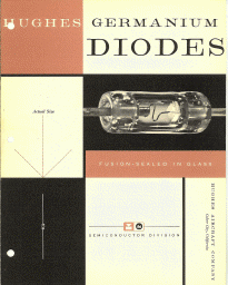
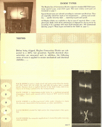
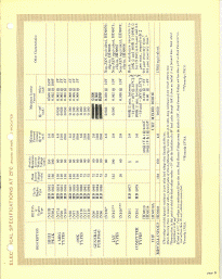
Hughes Germanium Diodes Hughes Aircraft Company - Semiconductor Division Hughes Germanium Diodes are point-contact crystal rectifiers with highly stable electrical and physical characteristics. They· are especially designed to meet the requirements of both commercial and military applications. To date, these diodes have been used successfully in hundreds of electronics and communications applications under severe environmental and operating conditions. Some of the characteristics essential to the success of these applications are: moisture resistance .. . thermal stability .. . electrical stability . . . subminiature size . . . thorough dependability. FEATURES 1 -gas-tight glass envelope is impervious to moisture, fumes, other harmful agents. 2 -actual dimensions: 0.265 by 0.130 inches maximum. 3 -operate without failure under physical shock or vibration. 4 -will withstand a wide range of operating temperatures. 5 -up to 1/4-inch from the body without special soldering precautions. CONSTRUCTION In addition to excluding moisture and other harmful agents, the fusion-sealed construction is mechanically stable. By matching the coefficients of expansion, even widely varying temperatures will produce only minor variations in the relative position of the elements. This mechanical stability is a vital factor in achieving the exceptionally stable electrical characteristics.The crystal is permanently bonded to its dumet lead by a conducting vitreous material . . . the catwhisker is welded to its lead . . . and the point of the catwhisker is welded to the crystal. Internal mechanical stability is achieved without danger of contamination from flux, waxes, impregnants or similar materials which might produce harmful vapors. Hughes Germanium Diodes are fusion-sealed in a one-piece glass envelope. This assures complete isolation of the active elements from damage or contamination caused by the penetration of moisture or other external agents. These diodes are small-less than 1/8-inch in diameter and approximately >i-inch long. This makes possible significant reductions in the size of electronic assemblies and equipment. Their small size-combined with light mass and great rigidity-enable them to withstand physical shock and vibration . They can be operated over an ambient temperature range of from -78°C to +90°C. Non-operating, they will suffer no permanent change at temperatures up to 150°C. This temperature range allows them to be soldered with an iron or by dip techniques up to 1/4-inch from the body. DIODE TYPES The Hughes line of Germanium Diodes comprises standard RETMA types, many special types, some JAN types. The more widely used types are tabulated on page 7. Special diode types are selected according to customer specifications. They are especially tested for: high or low temperatures . . . pulsing and switching . . . specific recovery time . . . matching in pairs and quads. All Hughes diodes are available as clip-in types if required. Here, a complete basic diode (with all its advantages) is adapted for clip-in service by mounting it in a package with more rigid terminal pins. (See dimensional drawing, page 2. These types are listed in the Table on page 7.) TESTED Before being shipped, Hughes Germanium Diodes are sub jected to a 100% test procedure. Specific electrical characteristics are measured and, in addition, the following series of tests is applied to ensure mechanical and electrical stability . . •page 2 General Information and Application Hints Because the use of semiconductor devices in electronic equipment is relatively new, many, characteristics and limitations, not covered by the type-defining ratings, are important in making the best possible selection and use of the units. The following brief discussion of some of these characteristics should prove helpful. Characteristics The characteristics of germanium diodes are interrelated in a complex manner. Generally, this complexity prohibits improvement in one characteristic without sacrifice in another. The types listed in this brochure have been selected as representative of the best compromises to fill circuit requirements, There are certain features, however, that should be noted. Usually, the low forward conductance diodes have superior. high temperature characteristics. Diodes which have forward current minimum ratings up to about 5 mA at 1 volt should be chosen when high back resistance at high temperatures is required. These diodes have high initial back resistance and they lose this resistance less rapidly than the higher conductance units as the temperature is increased.
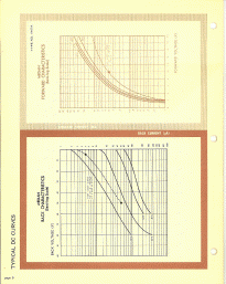
Another important consideration is the characteristic in the low reverse voltage region. As the temperature rises, the curve of back current drops sharply and then flattens out. This indicates that the effective back resistance at low voltages is considerably less than at higher voltages. (See curves on page 7.) This effect is more pronounced with high forward conductance diodes and is evident to some extent even at room temperature. Temperature exerts a very pronounced effect on the characteristics of all semiconductors, including germanium. Each application therefore, must be carefully analyzed to make sure the desired performance will be realized under any expected temperatures. The temperature of the crystal itself is the important factor. This is determined by ambient temperature and by the heat generated within the unit by the passage of current. As the temperature is raised, more and more electrons are made available for conducting current. This is a normal condition experienced in any material. In germanium diodes, it shows up as increased current, both forward and reverse, for a given set of voltage conditions. However, there is a greater increase, percentagewise, in reverse current than in forward current. So the effectiveness of the device-as indicated by the front to back ratio of current or resistance-decreases as the temperature is raised. (An example of this effect at various temperatures is shown by the characteristic curves on page 6.) In addition to lowering the back resistance, high temperatures reduce the peak inverse voltage-consequently, the maximum working voltage. An appreciable derating working voltage should be effected when high temperatures are expected. of resistance and they lose this resistance less rapidly than the higher conductance units as the temperature is increased.
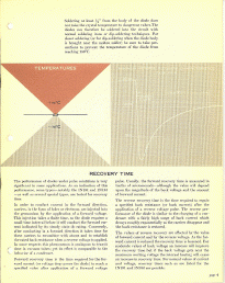
Operating Temperature Limits-A fairly basic limitation is imposed when the additional electrons made available by thermal agitation become significantly large compared to the number of current carriers which produce the rectifying action. The number of available current carriers is determined by the physical properties of the semiconductor. With germanium, this point is reached at about 100°C . . . so germanium diodes lose most of their rectifying properties at this temperature. NOTE: This effect is temporary and the diode will return to its room temperature performance as soon as the temperature is reduced. Non-Operating Temperature Limits-A, further danger from high temperature is encountered above 150°C (approximately). If the diode is raised to this temperature, a permanent change in characteristics may take place. Above this point repeated exposure to high temperatures will inevitably ruin the diode. If the diodes are encapsulated or if the equipment is baked, care should be taken not to exceed this temperature under any conditions. page 3 Soldering at least 1/4" from the body of the diode does not raise the crystal temperature to dangerous values. The diodes can therefore be soldered into the circuit with normal soldering irons or dip-soldering techniques. For closer soldering (or for dip-soldering when the diode body is brought near the molten solder) be sure to take precautions to prevent the temperature of the diode from reaching 150°C.RECOVERY TIME The performance of diodes under pulse conditions is very significant in some applications. As an indication of this performance, some types-notably the IN191 and. IN192 -as well as several special types, are tested for recovery time. In order to conduct current in the forward direction, carriers, in the form of holes or electrons, are injected into the germanium by the application of a forward voltage. This injection takes a finite time, so the diode requires a small time interval before it will conduct the forward current indicated by its steady state dc rating. Conversely, after conducting in a forward direction it takes time for these carriers to recombine with atoms and to establish the rated back resistance when a reverse voltage is applied. In some respects this phenomenon is analagous to transit time in vacuum tubes; yet its effect is comparable to the behavior of a condenser. Forward recovery time is the time required for the forward current (or voltage drop across the diode) to reach a specified value after application of a forward voltage pulse. Usually, the forward recovery time is measured in tenths of microseconds-although the value will depend upon the magnitude of the back voltage and the amount of forward current.The reverse recovery time is the time required to regain a specified back resistance (or back current) after the application of a reverse voltage pulse. The reverse performance of the diode is similar to the charging of a condenser with a fairly high surge of back current which decays roughly exponentially as the carriers disappear and the back resistance is restored. The values of reverse recovery are affected by the value of forward current and by the reverse voltage. As the forward current is reduced the recovery time is lessened. For moderate values of back voltage an increase will improve the recovery time but if the back voltage gets near the maximum working voltage the internal heating will cause an increase in recovery time. For normal values of current and voltage, recovery times such as are listed for the IN191 and IN192 are possible. page 4
|
